
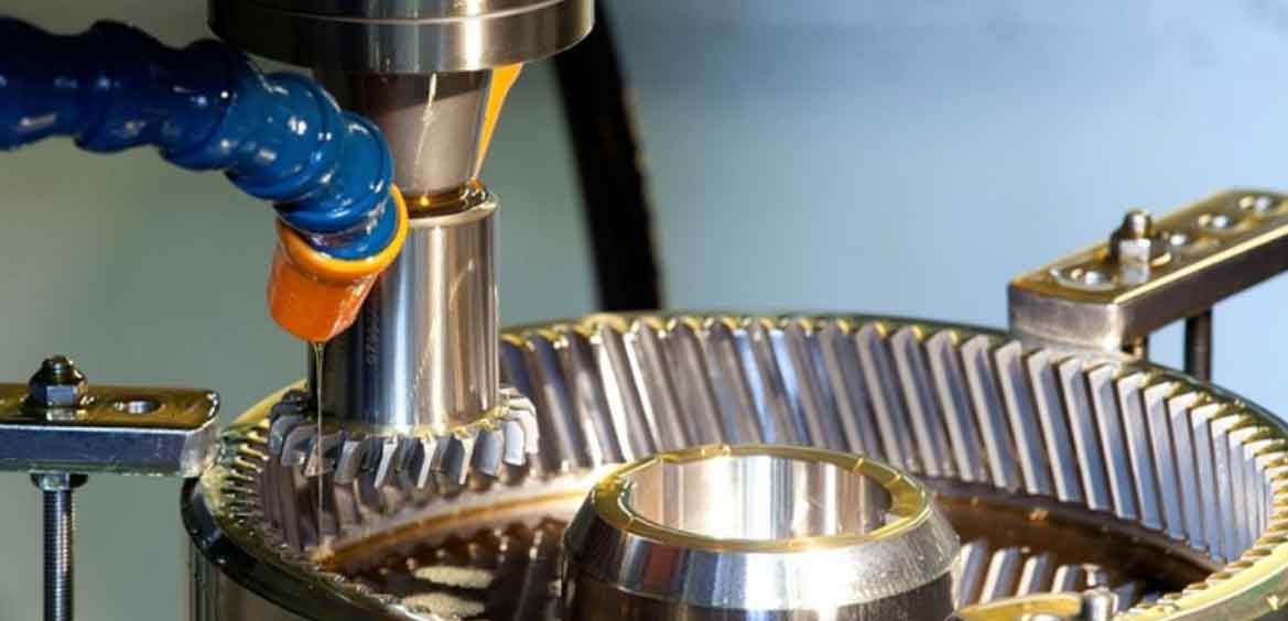
Gear shaping is a critical process for manufacturing sector teeth on rocker shafts in hydraulic recirculating ball power steering systems. These shafts feature complex geometry, with front and rear journals subjected to significant loads requiring reliable sealing. The intermediate sector gear, demanding high precision, necessitates gear shaping after rough milling. Manual positioning and clamping prove inefficient and inadequate for maintaining part accuracy. This necessitates specialized fixture design utilizing hydraulic power and automatic centering mechanisms to ensure quality and elevate automation in gear shaping operations.
Process Analysis for Rocker Shaft Gear Shaping
The rocker shaft, typically forged from 20CrMnTiH3 steel, comprises long and short journals connected by the sector gear. The sector teeth feature a conical top land, meaning the tooth profile varies axially, resulting in differing modification coefficients at each cross-section. Consequently, the gear shaping tool’s primary motion axis must be inclined relative to the workpiece axis. Critical technical requirements include:
- Runout ≤ 0.025 mm at the zero-modification section (R56.22 mm).
- High positional accuracy between the sector teeth and the journal diameters.
The process sequence prioritizes datum establishment: facing ends and drilling center holes. Subsequent operations include turning, rough milling of the sector teeth, semi-finishing and finishing gear shaping, spline hobbing on the long journal, heat treatment, center hole grinding, and finally, precision grinding of the journals. Achieving uniform stock removal during gear shaping requires restricting all six degrees of freedom. The primary challenge lies in selecting optimal locating datums for the gear shaping operation.
Locating Strategy
Effective locating is paramount for machining accuracy. Analysis identifies the forged sector gear sides, the sector shoulder face, and the long journal outer diameter (OD) as viable datums. The finalized locating scheme restricts six degrees of freedom:
- Long Journal OD: Locates in a V-block or collet, restricting four degrees of freedom (X, Y translation; X, Y rotation). This adheres to the datum coincidence principle, directly controlling position relative to the sector teeth.
- Sector Shoulder Face: Serves as the axial locating datum, restricting Z translation. The zero-modification section is positioned 5 mm from this shoulder, ensuring minimal error through datum coincidence.
- Sector Gear Side: A dedicated locating plate engages both sides simultaneously, establishing the sector symmetry plane and restricting Z rotation. This aligns with the datum unification principle, as the same feature was used for locating during rough milling.
This combination provides complete location, satisfies datum principles, and ensures consistent gear shaping results.
Special Fixture Design for Gear Shaping
The fixture is designed for use on CNC gear shaping machines, prioritizing automation, precision, and adaptability for group machining of different rocker shaft variants. Key components are modular.
Spring Collet Design
A spring collet centering and clamping mechanism is employed. This mechanism utilizes the elastic deformation of collet fingers to achieve simultaneous centering and clamping upon axial movement relative to a matching taper. The custom collet features:
- A precisely ground internal bore matching the rocker shaft’s long journal OD (e.g., Ø51.1 mm for a specific variant).
- An external taper (typically 15° included angle).
- A tail section designed for positive connection to a hydraulic cylinder piston rod via a transverse pin.
Adaptation to different shaft diameters is achieved by replacing the collet.
Taper Sleeve Design
The taper sleeve interfaces with the spring collet. Its critical features include:
- An internal taper matching the collet’s external taper (15° included angle).
- High-precision grinding of the taper bore, ensuring concentricity ≤ 0.01 mm with its mounting datum.
- Final lapping with the collet to guarantee >80% contact area.
The sleeve mounts rigidly within the fixture body. Adapting to different collets requires changing the sleeve.
Clamping Mechanism & Force Analysis
A hydraulic cylinder provides the clamping force. Process parameters for semi-finishing and finishing gear shaping are distinct. Force calculations focus on the more demanding semi-finishing stage:
| Parameter | Symbol | Value | Unit |
|---|---|---|---|
| Cutting Speed | Vc | 204 | m/min |
| Feed Rate | f | 0.33 | mm/stroke |
| Depth of Cut | ap | 2.5 | mm |
| Specific Cutting Force | kc | 1962 | N/mm² |
The main cutting force (axial force, Fc) and feed force (tangential force, Ff) are calculated:
Chip Cross-Sectional Area:
$$ A_D = a_p \times f = 2.5 \text{mm} \times 0.33 \text{mm} = 0.825 \text{mm}^2 $$
Main Cutting Force (Fc):
$$ F_c = k_c \times A_D \times K_{\text{correction}} = 1962 \text{N/mm}^2 \times 0.825 \text{mm}^2 \times 1.33 \approx 2153 \text{N} $$
Feed Force (Ff): (Typically 0.4 * Fc)
$$ F_f = 0.4 \times F_c = 0.4 \times 2153 \text{N} = 861.2 \text{N} \approx 861 \text{N} $$
Torque due to Feed Force (Me): (ra = 55.25 mm for example shaft)
$$ M_e = F_f \times r_a = 861 \text{N} \times 0.05525 \text{m} = 47.57 \text{N·m} $$
The radial clamping force (F) required at the journal OD (radius r = 27.5 mm) to prevent slippage under torque and axial force is:
$$ F = \frac{K \times M_e}{f \times r} $$
Where K = Safety Factor (1.8), f = Coefficient of Friction (0.15)
$$ F = \frac{1.8 \times 47.57}{0.15 \times 0.0275} = \frac{85.626}{0.004125} \approx 20758 \text{N} $$
Calculate elastic force per collet finger (Rc ≈ 474 N empirically). The required axial hydraulic force (Q) to actuate the collet is:
$$ Q = (F + R_c) \tan(\alpha + \rho_1) + F \tan \rho_2 $$
Where:
- α = Collet half-cone angle (7.5°)
- ρ1 = Friction angle collet/sleeve (tanρ1=0.2, ρ1≈11.5°)
- ρ2 = Friction angle collet/workpiece (tanρ2=0.15, ρ2≈8.5°)
$$ Q = (20758 + 474) \tan(7.5^\circ + 11.5^\circ) + 20758 \tan(8.5^\circ) $$
$$ Q = (21232) \tan(19^\circ) + 20758 \tan(8.5^\circ) $$
$$ Q \approx 21232 \times 0.3443 + 20758 \times 0.1494 $$
$$ Q \approx 7309 + 3101 \approx 10410 \text{N} $$
A hydraulic cylinder with a bore ≥80 mm at 3.5 MPa system pressure (providing ~17.94 kN force, accounting for 80% efficiency) is sufficient for Q ≈ 10.41 kN.
Fixture Components and Operation
The fixture comprises:
- Fixture Body: Mounts directly to the gear shaping machine table.
- Taper Sleeve: Fixed within the body via screws.
- Spring Collet: Sits within the taper sleeve, connected to the hydraulic cylinder piston rod via a pin.
- Locating End Cap: Secures the top of the taper sleeve/collet assembly, incorporates a key.
- Locating Plate: Features a U-slot for shaft clearance and two precision pins. Its base has a keyway matching the end cap’s key.
- Stop Screw: Engages a groove in the collet shank to limit downward travel and prevent over-clamping.
| Component | Primary Function | Adaptability Feature |
|---|---|---|
| Fixture Body | Structural base, machine interface | Fixed |
| Taper Sleeve | Interface for collet actuation | Replaceable per collet size |
| Spring Collet | Centering & clamping workpiece | Replaceable per shaft diameter |
| Locating End Cap | Axial constraint, key for plate | Fixed or replaceable per collet stack height |
| Locating Plate | Angular positioning via sector sides | Replaceable per sector geometry |
Workflow:
- The operator places the rocker shaft (long journal down) into the fixture.
- The locating plate is manually positioned: the U-slot clears the short journal, and the plate’s keyway slides onto the end cap’s key.
- Simultaneously, the two pins on the plate contact both sides of the sector gear, establishing angular position.
- The hydraulic cylinder is activated, pulling the collet down into the taper sleeve. The collet fingers contract, centering and clamping the long journal OD securely.
- The operator removes the locating plate to prevent interference with the gear shaping tool.
- The CNC gear shaping cycle commences.
- After machining, the cylinder retracts, releasing the collet’s grip, and the finished part is removed.
Advantages and Conclusion
This specialized fixture design effectively addresses the challenges of rocker shaft gear shaping:
- Enhanced Precision: Spring collet provides high concentricity (< 0.01 mm typical). Precise locating (shoulder face, sector sides) minimizes datum errors.
- Increased Efficiency & Automation: Hydraulic clamping drastically reduces manual handling time compared to mechanical clamps. Integrated workflow allows fast loading/unloading.
- Improved Consistency: Automated clamping force ensures repeatable holding power, critical for consistent gear shaping quality under cutting forces.
- Group Machining Capability: Modular design (replaceable collets, sleeves, plates) enables adaptation to various rocker shaft models with minimal downtime, reducing fixture inventory costs.
- Robustness: Designed to withstand significant gear shaping forces calculated (Fc > 2150 N, Me > 47 Nm). Stop screw prevents collet over-travel.
The integration of a hydraulically actuated spring collet centering mechanism within a modular fixture structure provides a high-precision, efficient, and adaptable solution for the demanding gear shaping process of steering gear rocker shafts. This design significantly contributes to achieving the required gear quality while boosting productivity and automation levels in high-volume manufacturing environments. The principles of optimized locating, automated power clamping, and modularity for group technology are widely applicable to complex shaft component machining.