
Based on the design of three-axis linkage gear cutting mechanism, the two-axis linkage gear cutting mechanism is designed. The designed mechanism also needs a manual tilting CNC rotary table mechanism. The purpose is to manually adjust the base cone of different spiral bevel gears to be tangent to the horizontal plane, and install the gear blank on the working plane of the rotary table to control the rotation movement of the bevel gear blank. The difference from the three-axis linkage gear cutting motion is that in the three-axis linkage gear cutting process, one linkage motion is the rotation motion of the gear blank around the end point of the circular arc blade, while the feed motion of the two-axis linkage gear cutting machining in the tooth height direction is the rotation motion of the gear blank around the apex of the base cone. Therefore, the three-axis linkage mechanism moves in a straight line on the basis of horizontal rotary table – c-axis rotation; In order to ensure that the tooth blank can rotate around the apex of the base cone and realize the feed movement in the direction of tooth height, the horizontal rotary table must be installed on the linear moving mechanism. The schematic diagram of two axis linkage mechanism and feed mechanism required for gear cutting is shown in the figure.
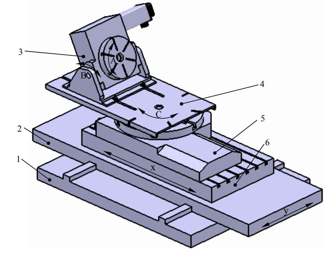
In the figure: 1 horizontal worktable base, 2 Y axis moving platform, 3 manual tilting CNC rotary worktable, 4 connecting plate, 5 horizontal rotary worktable and 6 x axis moving platform.
Before the two axis linkage gear cutting, the initial position must be determined for the machining of different spiral bevel gears. First of all, it is necessary to ensure that the base cone of the spiral bevel gear blank to be processed is tangent to the horizontal plane, and manually adjust the tilt angle of the workbench of mechanism 3 to make it equal to the base cone angle of the spiral bevel gear to be processed δ b. And lock it. Secondly, it must be ensured that the base cone apex of the bevel gear to be processed is located on the rotating shaft of the horizontal rotary table of mechanism 5, which can be realized by manually adjusting the relative position of the tilting rotary table of mechanism 3 on the connecting plate. Finally, by controlling the movement of x-axis and y-axis, the blade point is located at the initial position of feed. On the basis of the above work, the combined movement of the tooth blank along the x-axis direction and the rotation of the tooth blank around the a-axis can be controlled by NC program to realize the milling of the tooth surface of spiral bevel gear. When feeding in the direction of tooth height is required after machining a tool, it is realized by controlling the rotation movement of C axis.