
The main factors causing transmission errors of spiral bevel gears include the quasi conjugate characteristics of the tooth surface, deformation caused by loading, installation error and machining error, which are defined as follows: when the pinion is moving at a uniform speed, the difference between the actual meshing angle and the theoretical meshing angle of the big gear can be expanded by Taylor’s second-order to obtain a parabolic transmission error curve, as shown in Figure 1. The specific expression is:
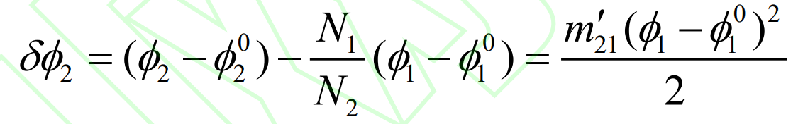
Where, N1 and N2 are the number of small and large teeth respectively; Φ 1、 Φ 2 is the current meshing angle of the small and large wheels respectively; Φ 01、 Φ 02 is the initial meshing angle of small and large wheels respectively; M ’21 is the first gear ratio derivative.
Spiral bevel gear pair enters meshing at point a to exits meshing at point B, and point m represents the reference point of tooth surface design; Φ 1A 、 Φ 1b and Φ 1m respectively represents the meshing angle of the small wheel at the corresponding time; δ Te is the transmission error amplitude at the meshing conversion point, and its relationship with the first-order transmission ratio derivative is:
According to the simultaneous formula, the expression of the meshing angle of the large and small wheels is:
Based on this, the transmission error of spiral bevel gear can be pre controlled to meet the required meshing performance.
When the actual coincidence degree of spiral bevel gear pair is greater than one, multiple pairs of teeth will participate in meshing at the same time and bear the load together. The load distribution coefficient between teeth is defined as:
Where, p is the maximum load borne by the gear tooth at the moment of meshing; P is the total load transmitted by the spiral bevel gear pair.