
I approach the design of a straight bevel gear differential for a farm transport vehicle as a complete system problem: the differential must transfer engine torque to the wheels, permit the two wheels to rotate at different speeds during a turn, and remain compact enough to fit inside the final drive housing. My first concern is therefore not a single gear tooth, but the relationship among the differential calculation torque, the planet gear count, the spherical radius of the planet gears, the pitch cone distance, and the geometry of the straight bevel gear pair. I use the straight bevel gear differential because its teeth are simple to manufacture, its axial positioning is straightforward, and its behavior is predictable under the low-to-moderate speeds typical of farm transport vehicles. In the following sections I describe the parameter selection, geometry calculation, strength check, and a complete numerical example for a straight bevel gear differential.
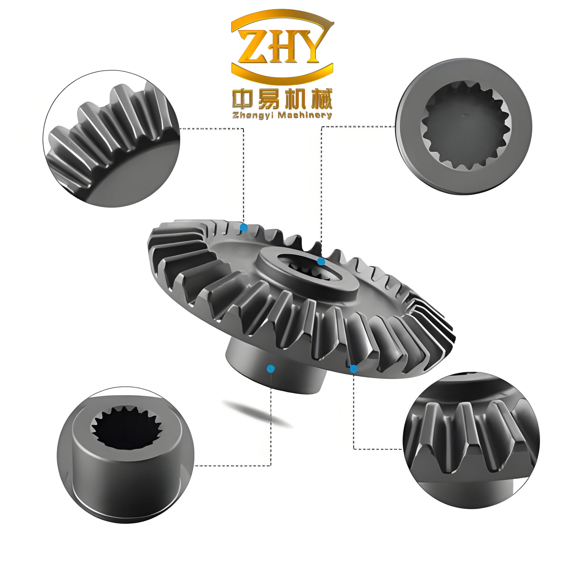
1. Differential torque and basic arrangement
I define the differential calculation torque as the smaller of two reference torques:
$$T_d = \min(T_{ce}, T_{cs})$$
Here \(T_{ce}\) is the torque derived from engine and driveline conditions, and \(T_{cs}\) is the torque derived from adhesion or traction limits. For a farm transport vehicle, this choice prevents the straight bevel gear differential from being sized by an unrealistically high stall torque that the tires cannot transmit. The differential housing transmits a torque \(T_0\), and I normally take \(T_0 = T_d\) for the main sizing calculations. The planet gear number \(n\) is usually four for freight and farm vehicles. A four-planet straight bevel gear differential gives good load sharing, compactness, and assembly symmetry. I use the following relationship for assembly: the sum of the teeth of the two side gears must be divisible by the number of planet gears. Because the two side gears normally have equal tooth numbers \(Z_2\), I require
$$ \frac{2 Z_2}{n} \in \mathbb{Z} $$
This condition ensures that all planet gears can be spaced equally and simultaneously mesh with both side gears. It is a simple but critical rule for any straight bevel gear differential.
| Symbol | Meaning | Typical choice or range |
|---|---|---|
| \(n\) | Number of planet gears | 4 for farm and freight vehicles |
| \(R_B\) | Planet gear spherical radius | Calculated from \(T_d\) |
| \(K_B\) | Spherical radius coefficient | 2.5 to 3.0; smaller for road vehicles |
| \(A_0\) | Pitch cone distance | \((0.98 \sim 0.99)R_B\) |
| \(Z_1\) | Planet gear tooth number | At least 10, preferably small |
| \(Z_2\) | Side gear tooth number | 14 to 25 |
| \(Z_2/Z_1\) | Tooth ratio | 1.5 to 2.0 |
| \(\alpha\) | Pressure angle | \(22^\circ30’\) |
| \(h_a^*\) | Addendum coefficient | 0.8 |
| \(d\) | Planet gear shaft diameter | Calculated from bearing stress |
| \(L\) | Support length on shaft | \(L = 1.1d\) |
2. Spherical radius and pitch cone distance
I calculate the planet gear spherical radius \(R_B\) with the empirical formula
$$R_B = K_B \sqrt[3]{T_d}$$
where \(T_d\) is in \(\mathrm{N \cdot m}\) and \(R_B\) is in millimeters. For a road-use farm vehicle I select the smaller end of the \(K_B\) range to reduce the size and mass of the straight bevel gear differential. Once \(R_B\) is known, I determine the pitch cone distance \(A_0\) from
$$A_0 = (0.98 \sim 0.99)R_B$$
The pitch cone distance is the fundamental length that controls the module, the tooth height, and the overall envelope of the straight bevel gear set. I prefer to round \(R_B\) and \(A_0\) to convenient values after the first calculation because the final module and tooth proportions must be practical for cutting and lapping. The following table summarizes my selection logic.
| Step | Quantity | Formula or rule | Design intent |
|---|---|---|---|
| 1 | \(n\) | 4 | Balanced load, simple assembly |
| 2 | \(T_d\) | \(\min(T_{ce},T_{cs})\) | Avoid oversizing |
| 3 | \(R_B\) | \(K_B \sqrt[3]{T_d}\) | Set the spherical envelope |
| 4 | \(A_0\) | \((0.98 \sim 0.99)R_B\) | Set the pitch cone distance |
| 5 | \(Z_1\) | \(Z_1 \ge 10\) | Maintain tooth strength |
| 6 | \(Z_2\) | \(14 \le Z_2 \le 25\) | Match ratio and assembly |
| 7 | \(Z_2/Z_1\) | 1.5 to 2.0 | Balance size and speed ratio |
| 8 | \(\alpha\) | \(22^\circ30’\) | Common farm vehicle tooth form |
3. Tooth number selection for the straight bevel gear differential
For the straight bevel gear differential, I choose the planet gear tooth number \(Z_1\) as small as practical, but not below 10. A smaller \(Z_1\) allows a larger module for the same pitch cone distance, which increases bending strength. However, if \(Z_1\) becomes too small, undercut and interference become difficult to control. I usually begin with \(Z_1 = 10\) or \(11\). The side gear tooth number \(Z_2\) is selected in the range 14 to 25. The ratio \(Z_2/Z_1\) should lie between 1.5 and 2.0. In addition, I must satisfy the assembly condition described earlier. The following table gives several feasible combinations for a four-planet straight bevel gear differential.
| \(Z_1\) | \(Z_2\) | \(Z_2/Z_1\) | \(2Z_2\) | Divisible by \(n=4\)? |
|---|---|---|---|---|
| 10 | 16 | 1.60 | 32 | Yes |
| 10 | 18 | 1.80 | 36 | Yes |
| 11 | 18 | 1.64 | 36 | Yes |
| 11 | 20 | 1.82 | 40 | Yes |
| 12 | 20 | 1.67 | 40 | Yes |
| 12 | 22 | 1.83 | 44 | Yes |
| 13 | 22 | 1.69 | 44 | Yes |
| 13 | 24 | 1.85 | 48 | Yes |
4. Pitch cone angles and module
For a straight bevel gear differential with a shaft angle of \(90^\circ\), I calculate the pitch cone angles from
$$\gamma_1 = \arctan\left(\frac{Z_1}{Z_2}\right)$$
$$\gamma_2 = \arctan\left(\frac{Z_2}{Z_1}\right)$$
The module at the large end is obtained from the pitch cone distance and the tooth numbers:
$$m = \frac{2A_0}{Z_1}\sin\gamma_1 = \frac{2A_0}{Z_2}\sin\gamma_2$$
Because \(\gamma_1 + \gamma_2 = 90^\circ\), the two expressions are equivalent. I use the average of the two results if there is a small numerical difference caused by rounding. The module is then rounded to a standard value. For a farm transport vehicle, a module near 4 mm is common for the straight bevel gear differential when the differential torque is in the range of a few thousand newton-meters. The pitch diameters are
$$d_1 = m Z_1$$
$$d_2 = m Z_2$$
These diameters are nominal large-end values. The actual tooth profile is cut on the cone, so all heights and clearances must be measured relative to the pitch cone.
5. Pressure angle and tooth proportions
I normally use a pressure angle of \(22^\circ30’\) and an addendum coefficient of 0.8 for the straight bevel gear differential. This combination provides a good compromise between bending strength, contact strength, and cutting feasibility. The working tooth height is
$$h_g = 1.6m$$
The total tooth height is
$$H = 1.788m + 0.051$$
where the small constant accounts for clearance and manufacturing tolerance. The addendum heights for the planet gear and side gear are not equal. I use the following relations:
$$h_1′ = h_g – h_2’$$
$$h_2′ = \left(0.430 + \frac{0.370}{(Z_2/Z_1)^2}\right)m$$
Then the dedendum heights are
$$h_1” = 1.788m – h_1’$$
$$h_2” = 1.788m – h_2’$$
The radial clearance is
$$C = H – h_g = 0.188m + 0.051$$
These proportions ensure that the straight bevel gear differential has adequate root clearance and that the tooth tips do not interfere in the assembled position.
| Item | Formula | Remarks |
|---|---|---|
| Working tooth height | \(h_g = 1.6m\) | Common for farm vehicle gears |
| Total tooth height | \(H = 1.788m + 0.051\) | Includes clearance |
| Planet addendum | \(h_1′ = h_g – h_2’\) | Depends on ratio |
| Side gear addendum | \(h_2′ = \left(0.430 + \frac{0.370}{(Z_2/Z_1)^2}\right)m\) | Controls load sharing |
| Planet dedendum | \(h_1” = 1.788m – h_1’\) | Root strength |
| Side gear dedendum | \(h_2” = 1.788m – h_2’\) | Root strength |
| Radial clearance | \(C = 0.188m + 0.051\) | Prevents bottoming |
6. Cone angles, face width, and outer dimensions
After the addendum and dedendum are known, I calculate the root angles and face angles. The root angle for each gear is
$$\delta_1 = \arctan\left(\frac{h_1”}{A_0}\right)$$
$$\delta_2 = \arctan\left(\frac{h_2”}{A_0}\right)$$
The face angles are
$$\gamma_{01} = \gamma_1 + \delta_2$$
$$\gamma_{02} = \gamma_2 + \delta_2$$
The root angles are
$$\gamma_{R1} = \gamma_1 – \delta_2$$
$$\gamma_{R2} = \gamma_2 – \delta_2$$
I also calculate the outer diameters:
$$d_{01} = d_1 + 2h_1’\cos\gamma_1$$
$$d_{02} = d_2 + 2h_2’\cos\gamma_2$$
and the distances from the pitch cone apex to the gear outer edge:
$$x_{01} = \frac{d_2}{2} – h_1’\sin\gamma_1$$
$$x_{02} = \frac{d_1}{2} – h_2’\sin\gamma_2$$
The face width \(F\) is selected from
$$F = (0.25 \sim 0.30)A_0$$
and I always check that
$$F \le 10m$$
This upper limit prevents the tooth from becoming too slender at the small end. For a straight bevel gear differential, the face width strongly affects the bending stress because the root thickness decreases toward the cone apex. I therefore keep the face width near the lower end of the range when the differential torque is high, and near the upper end when the envelope must be compact.
| Quantity | Formula | Purpose |
|---|---|---|
| Root angle, planet | \(\delta_1 = \arctan(h_1”/A_0)\) | Cutting angle |
| Root angle, side gear | \(\delta_2 = \arctan(h_2”/A_0)\) | Cutting angle |
| Face angle, planet | \(\gamma_{01} = \gamma_1 + \delta_2\) | Outer cone |
| Face angle, side gear | \(\gamma_{02} = \gamma_2 + \delta_2\) | Outer cone |
| Root angle, planet | \(\gamma_{R1} = \gamma_1 – \delta_2\) | Root cone |
| Root angle, side gear | \(\gamma_{R2} = \gamma_2 – \delta_2\) | Root cone |
| Outer diameter, planet | \(d_{01} = d_1 + 2h_1’\cos\gamma_1\) | Blank diameter |
| Outer diameter, side gear | \(d_{02} = d_2 + 2h_2’\cos\gamma_2\) | Blank diameter |
| Face width | \(F = (0.25 \sim 0.30)A_0\) | Tooth length |
7. Tooth thickness, backlash, and chord dimensions
For the straight bevel gear differential, I calculate the theoretical arc tooth thickness and then adjust it for backlash. A common approach is to start with
$$s_1 = s_2 = \frac{t}{2}$$
where
$$t = \pi m$$
The correction for addendum difference and pressure angle is applied as
$$s_2 = \frac{t}{2} – (h_1′ – h_2′)\tan\alpha – \tau m$$
where \(\tau\) is the tangential correction coefficient. The backlash \(B\) is selected from recommended tables. For a farm vehicle straight bevel gear differential, I usually choose the high-precision column when the gears are lapped and the housing stiffness is good. The chordal tooth thickness is
$$S_{x1} = S_1 – \frac{s_1^3}{6d_1^2} – \frac{B}{2}$$
$$S_{x2} = S_2 – \frac{s_2^3}{6d_2^2} – \frac{B}{2}$$
The chordal addendum is
$$h_{x1} = h_1′ + \frac{s_1^2 \cos\gamma_1}{4d_1}$$
$$h_{x2} = h_2′ + \frac{s_2^2 \cos\gamma_2}{4d_2}$$
These chordal dimensions are used for inspection and for setting the gear cutting tool. The following table gives the recommended backlash for different modules.
| Module \(m\) (mm) | Low precision \(B\) (mm) | High precision \(B\) (mm) |
|---|---|---|
| 2.11 to 2.54 | 0.076 to 0.127 | 0.051 to 0.102 |
| 2.54 to 3.18 | 0.102 to 0.203 | 0.076 to 0.127 |
| 3.18 to 4.23 | 0.128 to 0.254 | 0.102 to 0.152 |
| 4.23 to 5.08 | 0.152 to 0.330 | 0.127 to 0.178 |
| 5.08 to 6.35 | 0.203 to 0.405 | 0.152 to 0.203 |
| 6.35 to 7.25 | 0.254 to 0.508 | 0.178 to 0.228 |
| 7.25 to 8.47 | 0.305 to 0.559 | 0.203 to 0.279 |
| 8.47 to 10.15 | 0.381 to 0.635 | 0.254 to 0.330 |
| 10.15 to 12.7 | 0.508 to 0.762 | 0.305 to 0.406 |
| 12.7 to 14.5 | 0.508 to 1.016 | 0.356 to 0.457 |
| 14.5 to 15.9 | 0.635 to 1.143 | 0.406 to 0.559 |
| 16.9 to 20.3 | 0.889 to 1.397 | 0.457 to 0.660 |
| 20.3 to 25.4 | 1.143 to 1.651 | 0.508 to 0.762 |
8. Planet gear shaft diameter and support length
The planet gear shaft is a critical part of the straight bevel gear differential because it carries the planet gear and transmits the differential motion. I calculate the shaft diameter from the allowable bearing stress:
$$d = \sqrt{\frac{T_0 \times 10^3}{1.1 \sigma_c n r_d}}$$
where \(T_0\) is the differential housing torque in \(\mathrm{N \cdot m}\), \(n\) is the number of planet gears, \(r_d\) is the distance from the shaft center to the pitch cone apex at the planet gear support midpoint, and \(\sigma_c\) is the allowable compressive stress, normally taken as \(98\ \mathrm{MPa}\). I estimate \(r_d\) as approximately half of the average diameter at the midpoint of the side gear face width. If the side gear average diameter is about \(0.8d_2\), then
$$r_d \approx 0.4d_2$$
The support length of the planet gear on the shaft is
$$L = 1.1d$$
This length provides a favorable bearing pressure distribution and reduces the risk of edge loading. The following table summarizes the shaft design steps.
| Parameter | Formula | Typical value or note |
|---|---|---|
| Housing torque | \(T_0 = T_d\) | From differential torque |
| Planet count | \(n\) | 4 |
| Support radius | \(r_d \approx 0.4d_2\) | Based on side gear average diameter |
| Allowable stress | \(\sigma_c\) | 98 MPa |
| Shaft diameter | \(d = \sqrt{\frac{T_0 \times 10^3}{1.1 \sigma_c n r_d}}\) | Round to standard shaft size |
| Support length | \(L = 1.1d\) | Bearing length on shaft |
9. Bending strength of the straight bevel gear differential
Because the straight bevel gear differential operates only during turning, wheel speed difference, or wheel slip, I focus on bending strength rather than continuous contact fatigue. The gears spend most of their life stationary relative to one another, but when they do move, the load can be high. I use the bending stress formula
$$\sigma_w = \frac{2 T k_s k_m}{k_v m b_2^2 d_2 J n} \times 10^3$$
where:
| Symbol | Meaning | Selection |
|---|---|---|
| \(T\) | Side gear calculation torque | \(T = 0.6T_0\) |
| \(k_s\) | Size factor | Calculated from module |
| \(k_m\) | Load distribution factor | Usually 1.0 for a well-supported differential |
| \(k_v\) | Dynamic factor | Selected from main drive gear practice |
| \(m\) | Module | Large-end module |
| \(b_2\) | Side gear face width | From geometry |
| \(d_2\) | Side gear large-end pitch diameter | From geometry |
| \(J\) | Geometry factor | From standard charts |
| \(n\) | Number of planet gears | 4 |
I compare the calculated bending stress with the allowable stress. When \(T_0 = \min(T_{ce}, T_{cs})\), the allowable bending stress is often taken as \(980\ \mathrm{MPa}\). When \(T_0 = T_{cf}\), where \(T_{cf}\) is a fatigue or continuous torque, the allowable stress is usually much lower, for example \(210\ \mathrm{MPa}\). If the calculated stress exceeds the allowable value, I increase the pitch cone distance, increase the module, adjust the tooth numbers, or improve the material and heat treatment. Because the straight bevel gear differential is compact, the most effective change is often a small increase in \(R_B\) and \(A_0\), which raises the module and the tooth root thickness.
10. Design example for a farm transport vehicle
I now apply the procedure to a representative farm transport vehicle. I select four planet gears. I take the spherical radius coefficient \(K_B = 2.6\), and I use a differential calculation torque
$$T_d = \min(T_{ce}, T_{cs}) = 3165\ \mathrm{N \cdot m}$$
From the spherical radius formula,
$$R_B = 2.6 \sqrt[3]{3165} \approx 36.6\ \mathrm{mm}$$
I round this to \(R_B = 36\ \mathrm{mm}\). The pitch cone distance is
$$A_0 = 0.99 R_B \approx 35.6\ \mathrm{mm}$$
but after considering the physical envelope and standard tooling, I take \(A_0 = 37\ \mathrm{mm}\). I choose the planet gear tooth number \(Z_1 = 10\) and the side gear tooth number \(Z_2 = 16\). The ratio is
$$\frac{Z_2}{Z_1} = 1.6$$
and the sum of the two side gear teeth is \(32\), which is divisible by \(n = 4\). Therefore the assembly condition is satisfied. The pitch cone angles are
$$\gamma_1 = \arctan\left(\frac{10}{16}\right) \approx 32^\circ$$
$$\gamma_2 = \arctan\left(\frac{16}{10}\right) \approx 58^\circ$$
The large-end module is
$$m = \frac{2A_0}{Z_1}\sin\gamma_1 = \frac{2 \times 37}{10}\sin 32^\circ \approx 3.92\ \mathrm{mm}$$
I round this to \(m = 4.0\ \mathrm{mm}\). The pitch diameters become
$$d_1 = mZ_1 = 40\ \mathrm{mm}$$
$$d_2 = mZ_2 = 64\ \mathrm{mm}$$
I use a pressure angle of \(22^\circ30’\) and an addendum coefficient of 0.8. The planet gear shaft diameter is calculated from the shaft formula. With \(T_0 = 3165\ \mathrm{N \cdot m}\), \(n = 4\), \(r_d \approx 0.4d_2 = 25.6\ \mathrm{mm}\), and \(\sigma_c = 98\ \mathrm{MPa}\), I obtain
$$d = \sqrt{\frac{3165 \times 10^3}{1.1 \times 98 \times 4 \times 25.6}} \approx 17.4\ \mathrm{mm}$$
I round this to a standard shaft diameter and use a support length
$$L = 1.1d \approx 19\ \mathrm{mm}$$
The following table collects the main selected parameters.
| Parameter | Symbol | Value |
|---|---|---|
| Planet gear number | \(n\) | 4 |
| Spherical radius coefficient | \(K_B\) | 2.6 |
| Differential torque | \(T_d\) | 3165 N·m |
| Spherical radius | \(R_B\) | 36 mm |
| Pitch cone distance | \(A_0\) | 37 mm |
| Planet gear teeth | \(Z_1\) | 10 |
| Side gear teeth | \(Z_2\) | 16 |
| Tooth ratio | \(Z_2/Z_1\) | 1.6 |
| Pitch cone angle, planet | \(\gamma_1\) | \(32^\circ\) |
| Pitch cone angle, side gear | \(\gamma_2\) | \(58^\circ\) |
| Module | \(m\) | 4.0 mm |
| Pressure angle | \(\alpha\) | \(22^\circ30’\) |
| Planet shaft diameter | \(d\) | 17.4 mm |
| Support length | \(L\) | 19 mm |
11. Geometry results for the example
Using the formulas from the previous sections and a tangential correction coefficient \(\tau = -0.051\), together with a backlash \(B = 0.102\ \mathrm{mm}\), I calculate the geometry of the straight bevel gear differential. The working tooth height is
$$h_g = 1.6m = 6.400\ \mathrm{mm}$$
The total tooth height is
$$H = 1.788m + 0.051 = 7.203\ \mathrm{mm}$$
The side gear addendum is
$$h_2′ = \left(0.430 + \frac{0.370}{1.6^2}\right) \times 4.0 = 2.298\ \mathrm{mm}$$
The planet gear addendum is
$$h_1′ = h_g – h_2′ = 4.102\ \mathrm{mm}$$
The dedendum heights are
$$h_1” = 1.788m – h_1′ = 3.050\ \mathrm{mm}$$
$$h_2” = 1.788m – h_2′ = 4.854\ \mathrm{mm}$$
The radial clearance is
$$C = 0.188m + 0.051 = 0.803\ \mathrm{mm}$$
The root angles are
$$\delta_1 = \arctan\left(\frac{3.050}{37}\right) \approx 4.621^\circ$$
$$\delta_2 = \arctan\left(\frac{4.854}{37}\right) \approx 7.330^\circ$$
The face angles are
$$\gamma_{01} = 32^\circ + 7.330^\circ = 39.330^\circ$$
$$\gamma_{02} = 58^\circ + 7.330^\circ = 65.330^\circ$$
The root angles are
$$\gamma_{R1} = 32^\circ – 7.330^\circ = 24.670^\circ$$
$$\gamma_{R2} = 58^\circ – 7.330^\circ = 50.670^\circ$$
The outer diameters are
$$d_{01} = 40 + 2(4.102)\cos 32^\circ \approx 46.957\ \mathrm{mm}$$
$$d_{02} = 64 + 2(2.298)\cos 58^\circ \approx 66.436\ \mathrm{mm}$$
The pitch cone apex distances are
$$x_{01} = \frac{64}{2} – 4.102\sin 32^\circ \approx 27.368\ \mathrm{mm}$$
$$x_{02} = \frac{40}{2} – 2.298\sin 58^\circ \approx 16.854\ \mathrm{mm}$$
The face width is selected as
$$F = 0.30A_0 = 11.100\ \mathrm{mm}$$
and the check \(F \le 10m = 40\ \mathrm{mm}\) is clearly satisfied. The following table summarizes the geometry results.
| Item | Symbol | Value |
|---|---|---|
| Working tooth height | \(h_g\) | 6.400 mm |
| Total tooth height | \(H\) | 7.203 mm |
| Planet addendum | \(h_1’\) | 4.102 mm |
| Side gear addendum | \(h_2’\) | 2.298 mm |
| Planet dedendum | \(h_1”\) | 3.050 mm |
| Side gear dedendum | \(h_2”\) | 4.854 mm |
| Radial clearance | \(C\) | 0.803 mm |
| Planet root angle | \(\delta_1\) | \(4.621^\circ\) |
| Side gear root angle | \(\delta_2\) | \(7.330^\circ\) |
| Planet face angle | \(\gamma_{01}\) | \(39.330^\circ\) |
| Side gear face angle | \(\gamma_{02}\) | \(65.330^\circ\) |
| Planet root cone angle | \(\gamma_{R1}\) | \(24.670^\circ\) |
| Side gear root cone angle | \(\gamma_{R2}\) | \(50.670^\circ\) |
| Planet outer diameter | \(d_{01}\) | 46.957 mm |
| Side gear outer diameter | \(d_{02}\) | 66.436 mm |
| Planet apex distance | \(x_{01}\) | 27.368 mm |
| Side gear apex distance | \(x_{02}\) | 16.854 mm |
| Face width | \(F\) | 11.100 mm |
12. Strength check for the example
For the bending strength check, I use \(n = 4\), \(J = 0.257\), side gear face width \(b_2 = 11.3\ \mathrm{mm}\), side gear large-end pitch diameter \(d_2 = 64\ \mathrm{mm}\), dynamic factor \(k_v = 1.0\), size factor \(k_s = 0.629\), and load distribution factor \(k_m = 1.0\). The side gear calculation torque is
$$T = 0.6T_0 = 0.6 \times 3165 = 1899\ \mathrm{N \cdot m}$$
Substituting into the bending stress formula gives
$$\sigma_w = \frac{2 \times 1899 \times 0.629 \times 1.0}{1.0 \times 4.0 \times 11.3^2 \times 64 \times 0.257 \times 4} \times 10^3 \approx 755.5\ \mathrm{MPa}$$
When the allowable stress is \(980\ \mathrm{MPa}\), the calculated stress is below the limit, so the straight bevel gear differential satisfies the strength requirement for the high-torque case. If I use the fatigue torque \(T_{cf}\) and an allowable stress of \(210\ \mathrm{MPa}\), the calculated stress may exceed the allowable value by about 8 percent. In that situation I would either improve the material, use a better heat treatment, increase the pitch cone distance slightly, or choose a larger spherical radius coefficient. The following table compares the two strength cases.
| Case | Torque basis | Allowable stress | Calculated stress | Assessment |
|---|---|---|---|---|
| High-torque case | \(T_0=\min(T_{ce},T_{cs})\) | 980 MPa | 755.5 MPa | Satisfies requirement |
| Fatigue case | \(T_0=T_{cf}\) | 210 MPa | 227 MPa | About 8 percent over; improve material or geometry |
13. Assembly and manufacturing considerations
I treat the straight bevel gear differential as an assembly, not as four separate gears. The four planet gears must be equally spaced around the side gears. The side gear tooth sum must be divisible by four, as already discussed. The planet gear shaft holes must be aligned within a tight tolerance, because any misalignment shifts the load to one or two planet gears and reduces the effective strength of the straight bevel gear differential. I also pay attention to the following points:
| Area | Design action | Reason |
|---|---|---|
| Tooth contact | Lap the straight bevel gear pairs | Improve load sharing and reduce noise |
| Backlash | Select from high-precision table when possible | Control impact and lubrication |
| Shaft fit | Use a press fit or retained fit for planet gears | Prevent axial drift |
| Lubrication | Ensure oil reaches the planet gear thrust faces | Reduce wear during differential action |
| Housing stiffness | Use ribs near the side gear bearings | Maintain tooth contact under load |
| Material | Use carburized alloy steel for the straight bevel gear | High bending strength and wear resistance |
14. Sensitivity of the straight bevel gear differential to key parameters
I have found that the straight bevel gear differential is most sensitive to the pitch cone distance, the module, the face width, and the planet gear shaft diameter. A small increase in pitch cone distance raises the module and the root thickness, which lowers bending stress. However, it also increases the housing diameter and the mass. A small increase in face width increases the tooth contact area but can reduce the root thickness at the small end if carried too far. The planet gear shaft diameter must be large enough to keep the bearing stress below the allowable value, but if it becomes too large, the planet gear bore removes too much material from the planet gear. I therefore use the following sensitivity table as a guide during iteration.
| Parameter increased | Effect on size | Effect on bending stress | Effect on assembly |
|---|---|---|---|
| \(R_B\) | Increases | Decreases | May require larger housing |
| \(A_0\) | Increases | Decreases | Changes cone angles |
| \(m\) | Increases | Decreases | Requires standard tooling check |
| \(F\) | Slight increase | Decreases initially, then may increase | Must satisfy \(F \le 10m\) |
| \(Z_1\) | Depends on ratio | Usually decreases module | Must keep \(Z_1 \ge 10\) |
| \(Z_2\) | Depends on ratio | Affects ratio and module | Must satisfy \(2Z_2/n\) integer |
| \(d\) | Increases shaft | Little direct effect | Reduces planet gear web thickness |
15. Final design procedure in my own sequence
When I design a straight bevel gear differential from scratch, I follow this sequence:
| Step | Action | Output |
|---|---|---|
| 1 | Determine \(T_d = \min(T_{ce}, T_{cs})\) | Design torque |
| 2 | Select \(n = 4\) for a farm vehicle | Planet gear count |
| 3 | Choose \(K_B\) and calculate \(R_B\) | Spherical radius |
| 4 | Calculate \(A_0 = (0.98 \sim 0.99)R_B\) | Pitch cone distance |
| 5 | Select \(Z_1\) and \(Z_2\) | Tooth numbers |
| 6 | Check \(Z_2/Z_1\) and \(2Z_2/n\) | Feasible ratio and assembly |
| 7 | Calculate \(\gamma_1\), \(\gamma_2\), and \(m\) | Angles and module |
| 8 | Calculate \(h_g\), \(H\), \(h_1’\), \(h_2’\), \(h_1”\), \(h_2”\) | Tooth proportions |
| 9 | Calculate \(\delta_1\), \(\delta_2\), \(\gamma_{01}\), \(\gamma_{02}\), \(\gamma_{R1}\), \(\gamma_{R2}\) | Cone angles |
| 10 | Calculate \(d_{01}\), \(d_{02}\), \(x_{01}\), \(x_{02}\), \(F\) | Outer dimensions |
| 11 | Select backlash \(B\) and tangential correction \(\tau\) | Tooth thickness control |
| 12 | Calculate planet shaft diameter \(d\) and length \(L\) | Shaft design |
| 13 | Calculate bending stress \(\sigma_w\) | Strength check |
| 14 | Iterate if stress or envelope is unsatisfactory | Final straight bevel gear differential |
I repeat steps 3 through 13 until the straight bevel gear differential meets the strength target without exceeding the housing envelope. In most farm transport vehicle applications, the final module falls between 3.5 mm and 5 mm, the planet gear tooth number falls between 10 and 12, and the side gear tooth number falls between 16 and 22. The pressure angle remains \(22^\circ30’\), and the addendum coefficient remains 0.8. The resulting straight bevel gear differential is compact, robust, and suitable for the intermittent differential action that occurs during turns and wheel slip.
16. Closing view of the straight bevel gear differential
My overall conclusion is that the straight bevel gear differential is well matched to farm transport vehicles when the designer respects the assembly rule, chooses the spherical radius and pitch cone distance carefully, and checks bending strength rather than assuming continuous meshing. The straight bevel gear tooth form is easy to manufacture, the four-planet arrangement gives good load sharing, and the geometry can be adjusted by changing \(R_B\), \(A_0\), \(Z_1\), and \(Z_2\) without redesigning the entire axle. I use the formulas and tables above as a complete design chain: from \(T_d\) to \(R_B\), from \(R_B\) to \(A_0\), from \(A_0\) to \(m\), from \(m\) to the full straight bevel gear geometry, and finally from that geometry to the bending stress and shaft diameter. When the calculated stress is below the allowable value and the assembly condition is satisfied, the straight bevel gear differential is ready for detailed drafting, tooling selection, and prototype testing.