
1. Chemical composition analysis
Firstly, the chemical composition of the original forging is analyzed, and it is found that the chemical composition of the forging is within the required range, as shown in Table 1, which eliminates the possibility of grinding cracks due to the non-compliance of the chemical composition.

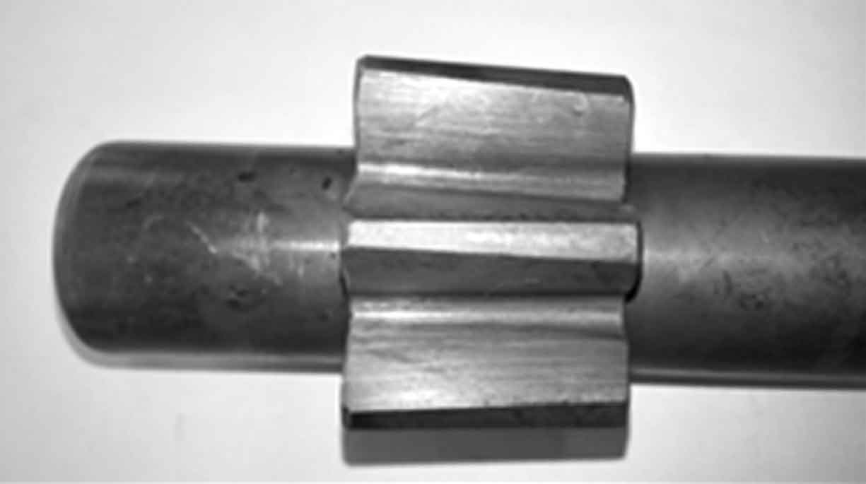
2. Macro morphology analysis of shaft teeth
With the help of magnetic particle flaw detector, magnetic particle flaw detection is carried out on the fan tooth surface before carburizing quenching, after carburizing quenching, before grinding and after grinding. The results are shown in Fig. 1 ~ Fig. 3. It can be seen that there are no micro grinding cracks on the tooth surface before carburizing and quenching and after carburizing and quenching; After grinding, a macro mesh grinding crack as shown in Fig. 3 appears on the fan tooth surface. The grinding crack extends from the tooth root to the involute tooth surface. Its overall trend distribution is perpendicular to the grinding direction and tends to be “parallel” along the involute tooth surface.


3. Microstructure analysis
Metallographic microscopic analysis is carried out on the same part of gears in different processing stages before carburizing quenching, after carburizing quenching, before grinding and after grinding. The results are shown in Fig. 4 ~ Fig. 6. It can be seen that the microstructure before carburizing and quenching is ferrite + pearlite, and the metallographic structure level is level 1 (Fig. 4); After carburizing and quenching, the structure before grinding is typical tempered martensite structure, the carbide presents dispersed distribution, the structure level is about 1.5, and the martensite structure level is 2 (Fig. 5); After gear grinding, take samples near the grinding crack on the surface of the sector gear and conduct metallographic structure analysis. As shown in Fig. 6, from outside to inside, it is “secondary quenched martensite” (white bright area) tempered troostite low-carbon martensite.


4. Microhardness analysis
The surface microhardness test and analysis reflect the microstructure change state of the material surface hardening layer from one side. The white bright layer is caused by the instantaneous increase of part surface temperature during grinding, resulting in the re austenitization of surface structure, rapid cooling under the action of coolant and “secondary quenching”. The microstructure is quenched martensite with high microhardness. After corrosion, it presents “white bright color” under metallographic microscope. The sub surface layer is located in the heat affected zone of the surface layer. Similarly, a medium and high temperature tempering is carried out, and the microhardness decreases obviously. As the test part moves inward, the heat affected effect decreases, the hardness gradually increases, and then decreases, as shown in Fig. 7. The abnormal trend of microhardness distribution curve of carburized layer reflects the abnormal structural changes of surface hardened layer.
