
Straight bevel gears are important mechanical components, and their main function, like general cylindrical gears, is to transmit torque through the meshing of gear tooth profiles. Compared to spur cylindrical gears, straight bevel gears have the following advantages:
① The installation axis of a straight bevel gear can be any angle from 0 ° to 90 °;
② Compared to cylindrical spur gears, straight bevel gears operate more smoothly and transmit greater torque;
③ The modulus of a straight bevel gear varies from one end of the full tooth width to the other.
Straight bevel gears are also used in pairs. When testing components of straight bevel gears, there are some testing parameters that require testing for individual straight bevel gears, such as tooth height, common normal length, chord tooth thickness, etc. However, there are other parameters that we must test when the straight bevel gears are paired and meshing with each other, such as cone angle detection, shaft intersection angle detection, contact spot detection, etc Detection of tooth surface backlash and tooth tip clearance, etc.
If paired straight bevel gears are assembled on the product without undergoing pairing inspection, once problems with tooth surface meshing are found, disassembly becomes more cumbersome. Generally, straight bevel gears and their matching drive shafts are assembled together through interference fit or transition fit through hot or cold assembly, resulting in a compact fit and inconvenient secondary disassembly. So this requires us to design a fixture for the meshing of straight bevel gears, to check the detection elements in advance under the meshing condition of straight bevel gears.
1. Product Introduction
ZHY Gear is one of the main mechanical manufacturers in China, including internal mixers, twin-screw extruders, flat vulcanization machines, tire vulcanization machines, and so on. The object of our research here is the main transmission component of the twin screw extruder, the synchronous straight bevel gear, with a specific model of 416 single hanging double cone twin screw extruder. As shown in Figure 1, it belongs to an equal top clearance straight bevel gear with 48 teeth, a pressure angle of 20 °, a dividing cone angle of 7 °, a large end modulus of 20 mm, a designed common normal length of 338.14 mm, and an assembly side clearance of 0.5 mm. In the actual assembly process, we often encounter such situations. After assembly, when using a feeler gauge to check the backlash between the meshing and non meshing surfaces of two matched straight bevel gears, it is found that the backlash at the large end of the straight bevel gear is different from that at the small end of the straight bevel gear, and the difference is relatively large. Therefore, when the straight bevel gear is engaged for transmission, there is insufficient contact in the tooth width direction, and the contact spot is smaller than the design requirements. This will cause different wear on the tooth surface of the matched straight bevel gear, with increased wear on the contact parts and no or slight wear on the non contact parts, seriously affecting the transmission effect and service life of the straight bevel gear. For such issues that affect assembly quality, relying solely on the quality inspection of a single piece of straight bevel gear cannot exclude all non conformities from the assembly process. Moreover, once an unqualified straight bevel gear is installed on the product, it is time-consuming and laborious for assembly workers to dismantle it, and it is easy to damage the self-aligning roller bearing or transmission shaft, This is the reason why we designed the meshing fixture for straight bevel gears.
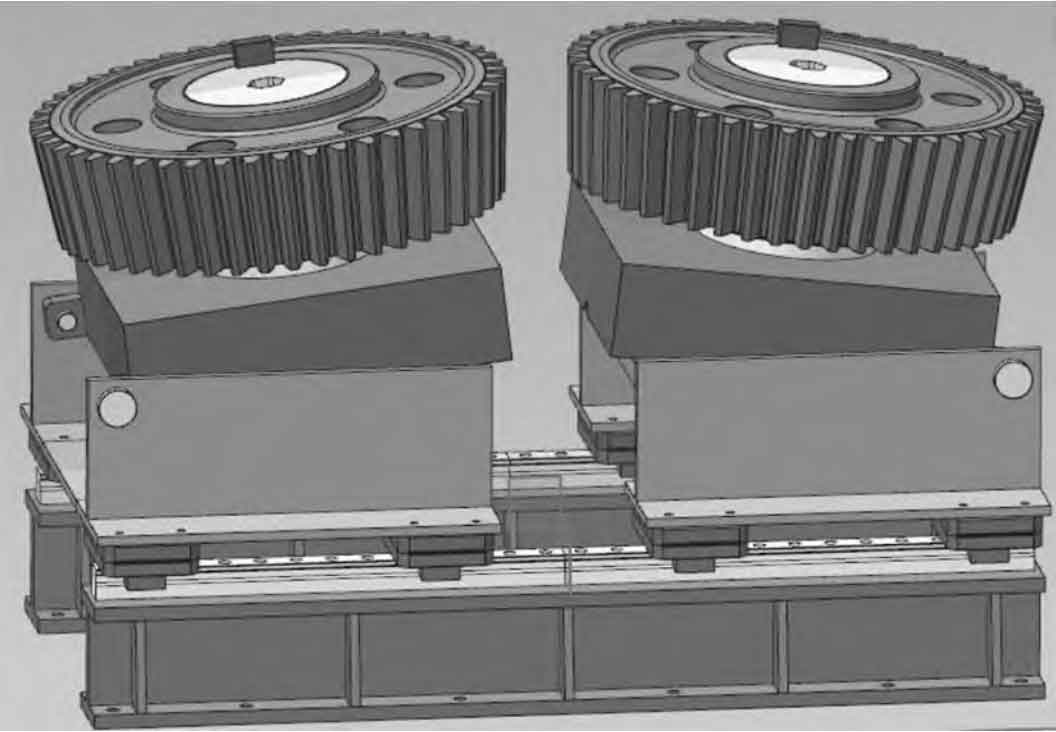
2. Fixture structure
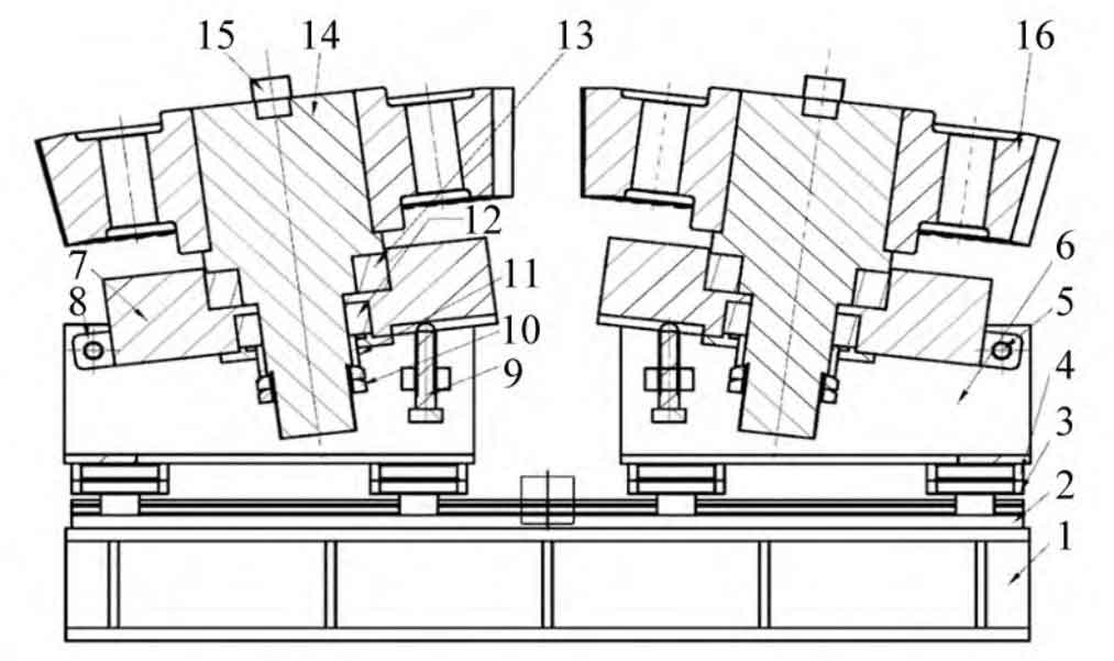
ZHY Gear designs straight bevel gear meshing fixture as shown in Figures 2 and 3:
3. Steps for tooling operation
(1) Before installing the straight bevel gear, restore the fixing block to a horizontal state.
(2) Install the straight bevel gear (serial number 16). It should be noted that the mating surface of the inner hole of the straight bevel gear needs to be coated with lubricating oil before installation; In addition, as a testing fixture, we need to modify the fit size between the outer diameter of the installation shaft and the inner hole of the spur bevel gear from the interference or transition fit designed on the drawing to a clearance fit, and appropriately reduce the outer diameter size of the installation shaft. These steps are helpful for us to smoothly install and disassemble straight bevel gears.
(3) Install the key (number 15) to secure the straight bevel gear to the mounting shaft and prevent a single straight bevel gear from freely rotating around the mounting shaft.
(4) Check the round nut (No. 10) at the end of the pre tightened installation shaft to prevent the inner and outer rings of the self-aligning roller bearing used for positioning under the fixture from loosening during assembly.
(5) According to the design of the bevel gear drawing, the bevel angle is achieved by adjusting the support bolt (No. 9) to drive the fixed block (No. 7) to rotate around the pin shaft (No. 5). When the dividing cone angle is 0 °, it is possible to pair and inspect spur cylindrical gears.
(6) Move the bracket (No. 6) along the guide rail to smoothly mesh the two straight bevel gears together.
(7) Lock the slider (No. 3) tightly to secure the bracket and prevent lateral displacement of the bracket along the guide rail (2).
(8) By installing the hexagonal wrench inner hole on the end face of the shaft (serial number 14), two meshing straight bevel gears can be easily manually rotated around the shaft.
4. Main parameters and application scope
(1) Overall dimensions: 2000 mm x 1 020 mm x 1 300 mm
(2) Application scope of tooling: spur cylindrical gears, straight bevel gears
(3) Adjustable taper angle range for tooling: 0-20 °
(4) Gear diameter range: Ф 800~ Ф 1200
(5) Maximum gear weight: 5 t/piece
5. Analysis of meshing detection for straight bevel gears
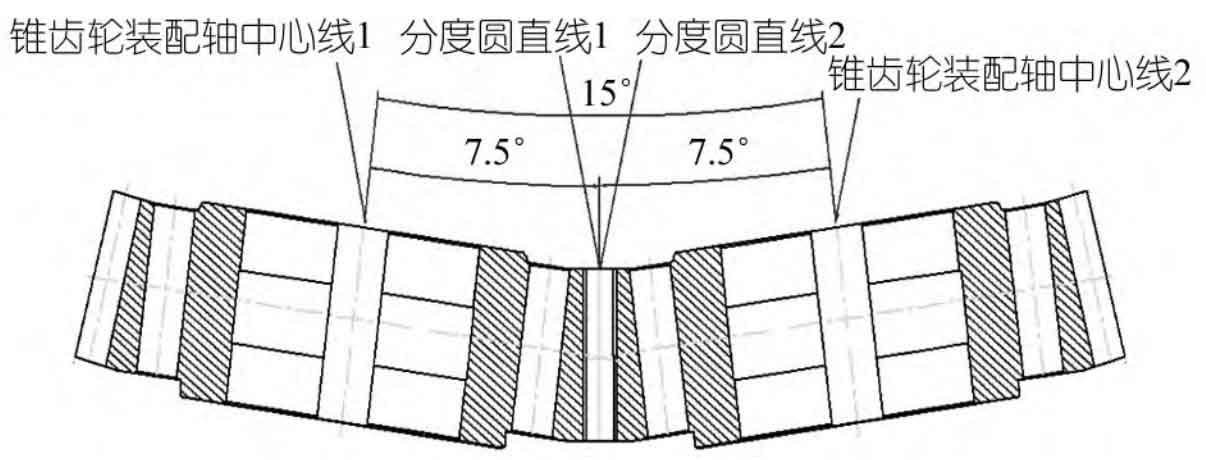
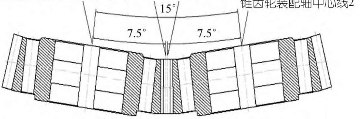
The meshing of straight bevel gears, apart from the factor of tooth shape, is mainly influenced by two parameters: cone pitch and the other important parameter is the dividing cone angle. The taper distance determines the position of a pair of meshing straight bevel gears on the rotation axis, just like the center distance parameter of a cylindrical gear. The difference is that the centers of the cylindrical gears are parallel to each other, while the centers of the straight bevel gears form a certain angle. Cone pitch is a parameter value assigned by the design, and we can adjust the backlash of the meshing tooth surface by adjusting the cone pitch. Moving towards the small end of the straight bevel gear reduces the backlash, while vice versa increases the backlash. However, this can only be achieved when the bevel angles of the two straight bevel gears are the same. If the bevel angles of the paired straight bevel gears are not consistent, The effect of adjusting the tooth surface clearance by adjusting the cone distance will disappear. The dividing cone angle is a parameter that reflects the angle between the center of straight bevel gear and the straight line of the dividing circle. It directly determines the size of the contact spot area on the tooth surface of two known straight bevel gears, thereby determining the quality of power transmission on the meshing surface. Practice has shown that during the assembly process of straight bevel gears, there are four situations that occur when dividing the cone angle:; The first type is the ideal meshing of straight bevel gears. As shown in Figure 4, the straight lines of the indexing circles of the two straight bevel gears will coincide, and the backlash on the tooth surface will be completely eliminated. The backlash on both the meshing and non meshing surfaces will be zero. In practical applications, considering the existence of machining errors and the tendency of meshing teeth to jam under zero backlash, this situation is generally not adopted.
The second type is the meshing of straight bevel gears in parallel, as shown in Figure 5. It refers to the fact that the backlash of the meshing surface of a straight bevel gear is zero before and after, while there is a certain amount of backlash left on the non meshing surface, and the backlash values of the straight bevel gear are equal before and after along the tooth width direction. The specific backlash value is determined by the designer based on the machining accuracy level and operating conditions of the straight bevel gear itself. If the measured backlash value of the actual paired straight bevel gear is larger than the design requirement, it indicates that the two gears need to move a certain distance along the axial term; On the contrary, if the measured backlash value is smaller than the design requirement, the two gears need to move outward along the axial position by a certain distance. This distance adjustment is usually achieved by adjusting the width of the two fixed distance sleeves installed in the front and rear positions of the straight bevel gear.
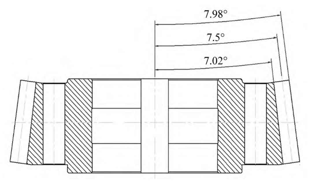
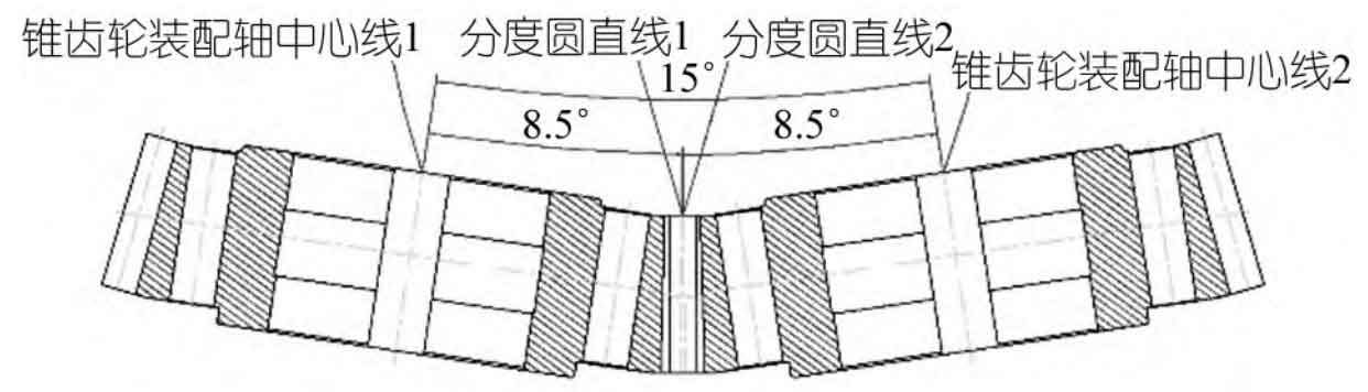
The third type is the meshing state of straight bevel gears with large bevel angles, as shown in Figure 6. In this state, the backlash value at the small end of the straight bevel gear measured with a feeler gauge is smaller than the backlash value at the large end of the straight bevel gear, and the backlash values on the meshing and non meshing surfaces of the large end teeth are not zero. This indicates that the meshing situation of such paired straight bevel gears is not ideal. Only a portion of the tooth surface at the small end of the straight bevel gear can effectively transmit power, which will inevitably lead to increased wear on the contact part of the tooth surface, greatly reducing the service life of the straight bevel gear, and irregular straight bevel gear meshing noise will occur during operation. Once this situation occurs, straight bevel gears can only be directly scrapped, or for some side clearance values with small deviations, they can be manually repaired and then downgraded for use as defective products.
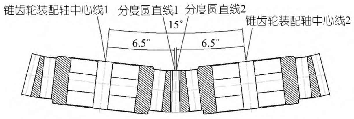
The fourth type is the meshing state of straight bevel gears when the dividing cone angle is too small, as shown in Figure 7. This state is exactly opposite to the previous situation. The small end backlash value of the straight bevel gear measured with a feeler gauge is greater than the large end backlash value of the straight bevel gear, and the backlash values of the small end tooth side meshing surface and non meshing surface are not zero. This indicates that only a portion of the tooth surface of the large end of the straight bevel gear is in normal contact, which can also cause the same problem as shown in Figure 6. The handling method can also refer to the third method.
6. Summary
It is very necessary to check the matching meshing of straight bevel gears, and its results cannot directly reflect whether a single quality requirement is qualified during the machining process of straight bevel gears. It is only an inspection of the assembly quality of straight bevel gear meshing. The meshing detection of straight bevel gears is not only directly affected by the tooth shape itself, but also mainly affected by the cone distance and the dividing cone angle. We can conduct single piece inspection and elimination of tooth profile through tooth profile templates; Cone pitch is a fixed value assigned by design, and once determined, it does not have any impact on the straight bevel gear itself; The only remaining determining factor is the dividing cone angle. Our dividing circle is a virtual circle, and it is difficult to measure its specific size in practice, let alone the dividing cone angle based on the dividing circle. This fixture can not only help us detect the tooth surface clearance size of two straight bevel gears before formal assembly, but also calculate and adjust the intercept of the straight bevel gears based on the actual measured side clearance value, in order to achieve the ideal meshing state of the straight bevel gears.