When machining the large gear of spiral bevel gear with forming method, the slight difference between the tooth profile angle A02 of the cutter head and the cone angle a f of the root of the large gear will cause the difference between the tooth profile on both sides of the large gear and the theoretical tooth profile, which is the unfavorable side of machining the large gear of spiral bevel gear with forming method. On the other hand, because there is no relative movement between the forming wheel and the large wheel when machining the large wheel of spiral bevel gear by forming method, the tooth surface shape of the large wheel of spiral bevel gear only depends on the relative position of the cutter head and the wheel blank. When the tooth angle of the cutter head is not equal to a f, it can be corrected by rotating the cutter head by a certain angle.
In order to make the inner blade and the outer blade have the same service life, the cutter head with the tooth shape angle on both sides equal to the average pressure angle a is usually used to process the formed spiral bevel gear wheel. At this time, the cutter head needs to rotate around the – 1 e axis:
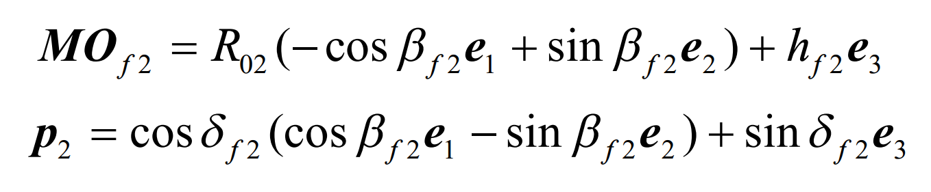
After the cutter head rotates DA2, due to the relativity of motion, rotating the cutter head around the – 1E axis DA2 can also be considered that the cutter head does not move and the wheel blank rotates DA2 around the 1E axis. According to Fig. 1, the expressions of the root cone vertex of 2 and axis 2 P of the large wheel blank of spiral bevel gear before rotation are as follows:
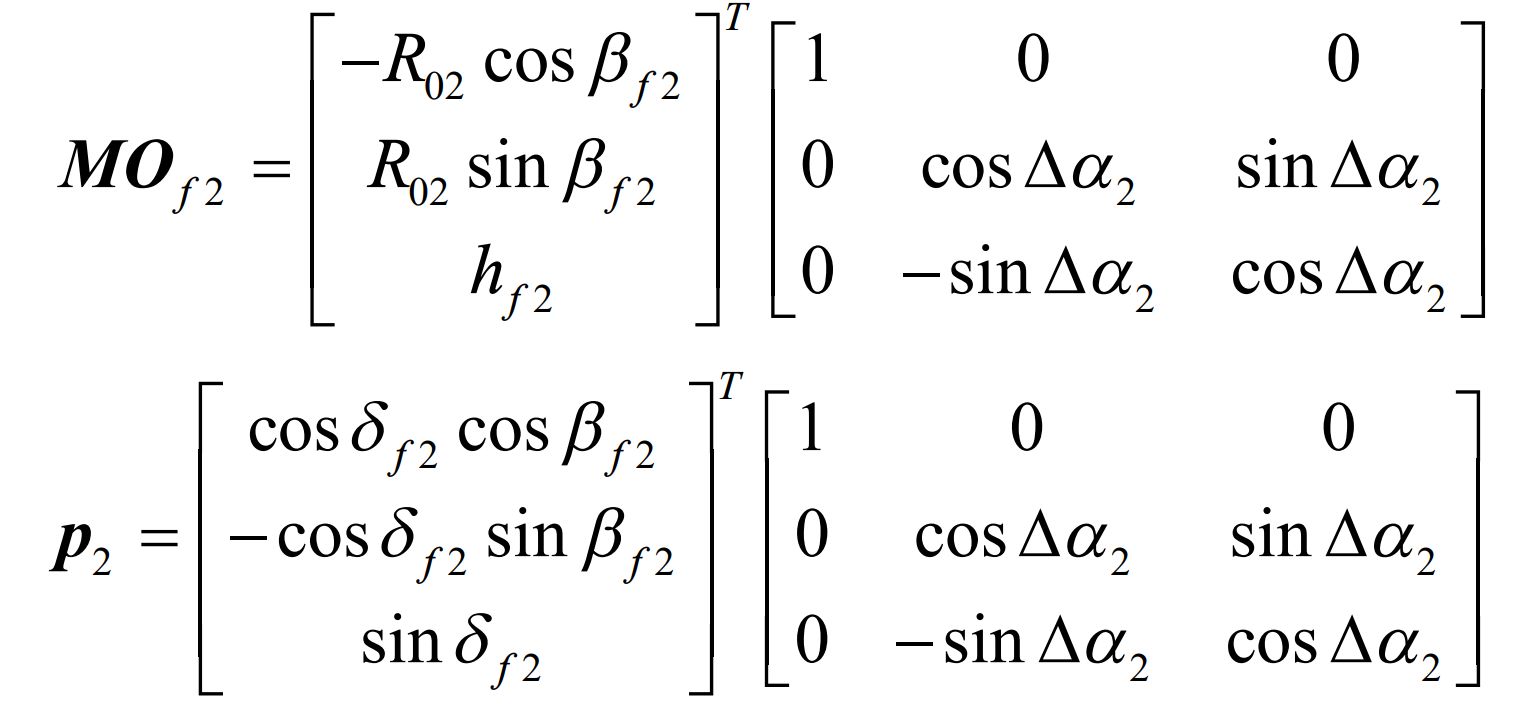
After the large wheel blank of spiral bevel gear rotates DA2 around 1E, it can be seen that:
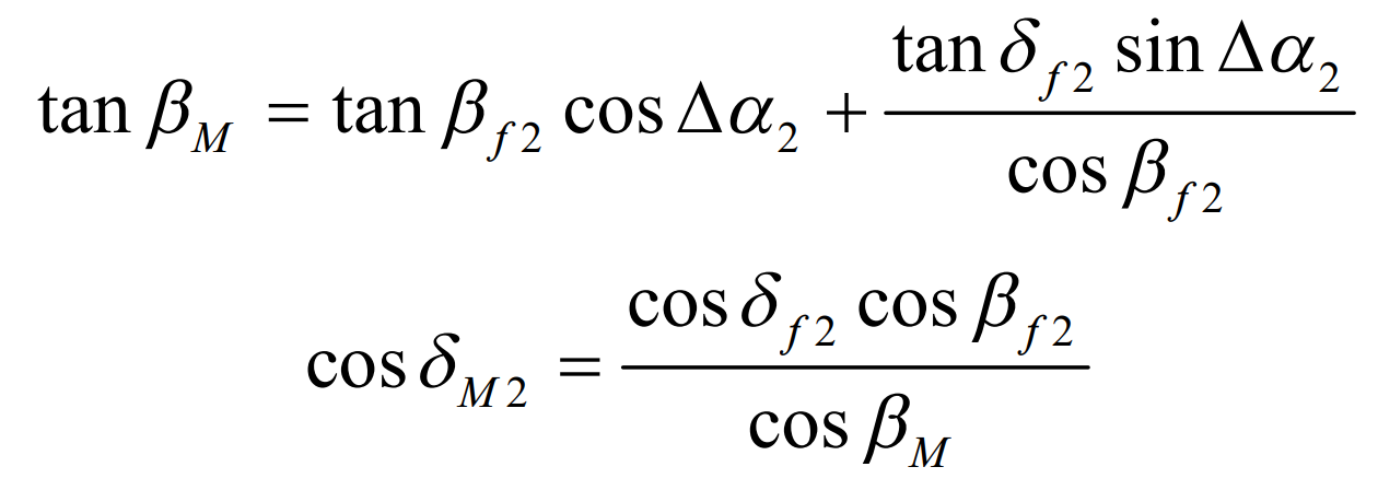
The situation of spiral bevel gear blank after rotation is shown in Figure 2. Suppose that the included angle between the axis of the large wheel and the plane of the machine tool of the gear milling machine after the rotation of the blank of the spiral bevel gear is M2 D, and the included angle between 1E and the horizontal direction MX is b m, which can be seen from the figure:
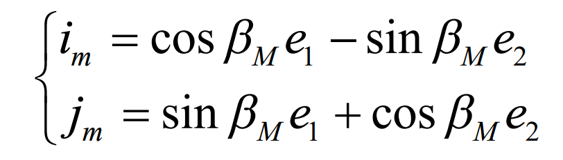
Therefore, the calculation formulas of B M and M 2 D can be solved:
It can also be seen from Figure 1 that the coordinates of the cutter head center ot are:
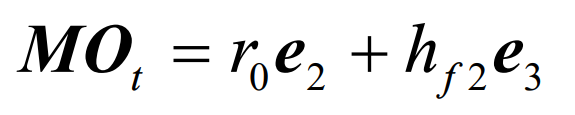
After the spiral bevel gear blank rotates, the vector from the cone angle vertex of the large root of the spiral bevel gear to the cutter head center ot shall be:

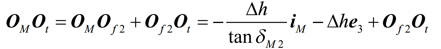
The center of the gear milling machine tool is the intersection om of the big wheel axis 2 P and the tool tip plane. The distance from the apex of the root cone of 2 to the plane of the machine tool can be obtained by projecting o of T 2 in the direction of 3e:
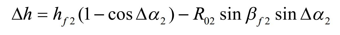
The vector from machine center om to cutter head center OT is determined by Figure 2: