In order to improve the dynamic performance of straight bevel gear system, it is necessary to solve the appropriate modification amount for the modification of straight bevel gear. If the amount of modification is too large, the bearing capacity of gear teeth will be reduced, which can not effectively reduce the vibration and impact of straight bevel gear transmission; If the modification amount is too small, the modification effect will not be ideal.
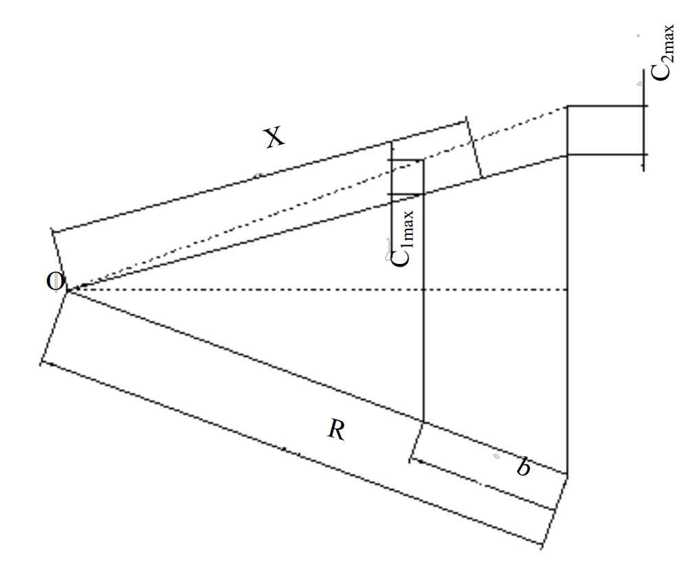
Generally, the circumferential displacement difference between the point on the meshing area in the tooth direction and the corresponding point away from the meshing area can be used to represent the deformation of large and small ends. After calculating the maximum deformation c1max of the big end of the tooth, the deformation at any place in the whole tooth direction can be solved according to the geometric relationship in the tooth direction of the straight bevel gear.
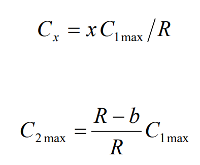
As the figure shows the geometric relationship in the tooth direction, the tooth deformation at the distance x from the apex of the cone and the maximum deformation at the small end of the tooth are as follows:
Where, R is the pitch of straight bevel gear and B is the tooth width of straight bevel gear.
When the angular velocity of the driving gear is 157rad / s, the deformation of the large end of the planetary gear and the half shaft gear are 21 respectively by using the finite element software μ M and 35 μ m。
The equidistant modification amount of tooth direction can be obtained by determining the drum modification amount, or by using the finite element software to analyze and calculate the difference of the angular displacement of the corresponding nodes of meshing teeth and non meshing teeth. The influence of tooth modification on the vibration equation of straight bevel gear must also be considered in the determination of tooth direction modification. The modified straight bevel gear also needs to be driven according to the gear vibration equation.
According to the recommendation of ISO standard, for the gear teeth with low accuracy requirements, the modification amount can generally be taken as 10 μ m<∆<40 μ m. In addition, the manufacturing error is about 5 ~ 10 μ m; For gear teeth with high accuracy and reliability requirements, the modification amount can generally be taken as 10 μ m <∆<25 μ m. In addition, the manufacturing error is about 5 ~ 10 μ m。
The calculation formula of shape modification given in ISO standard is:
Where, f β Xcv is the equivalent skew of straight bevel gear, which is the same as the skew F of unmodified straight bevel gear β The xcv is the same size.
The calculation formula recommended by Taylor Brown is:
Selecting a reasonable amount of tooth profile modification can improve the transmission performance of straight bevel gear to a certain extent, improve the load distribution in tooth direction and avoid the phenomenon of meshing stress concentration at the end of gear teeth.
The difference of angular displacement between meshing teeth and non meshing teeth of straight bevel gear is calculated by finite element analysis, and the tooth direction modification is 30 μ m。


