Abstract
The development and accuracy analysis of herringbone gear measurement software. By utilizing advanced measurement techniques and algorithms, the software is designed to measure various geometric errors of herringbone gears, including tooth profile, helix, tooth pitch, and alignment deviations. The software has been implemented on a CNC gear measurement center and has demonstrated good measurement accuracy and stability.

1. Introduction
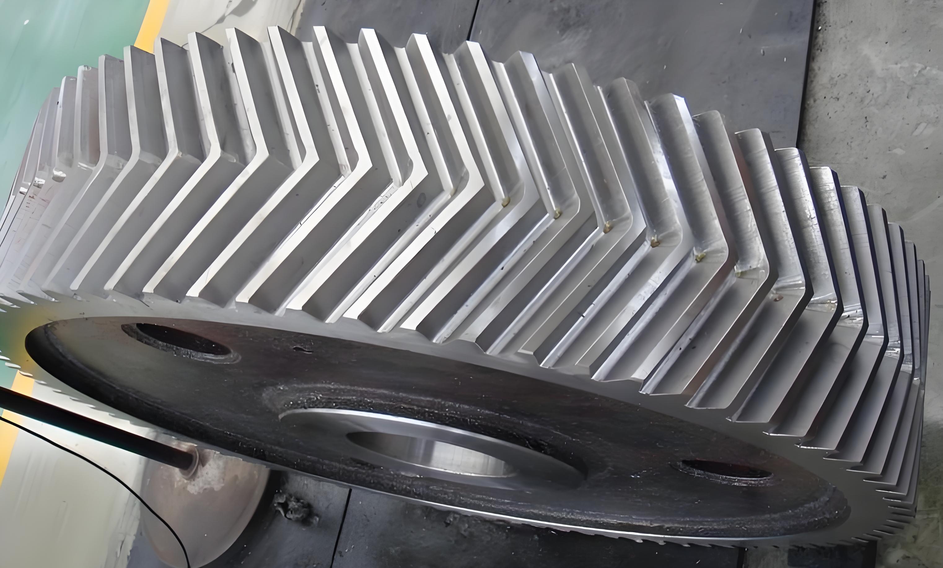
Herringbone gears are widely used in industrial applications due to their high efficiency and load-carrying capacity. However, the accurate measurement and evaluation of herringbone gears have always been a challenging task. Traditional measurement methods for cylindrical gears cannot be directly applied to herringbone gears due to their unique structure. Therefore, there is a need for specialized measurement software for herringbone gears.
2. Development of Herringbone Gear Measurement Software
2.1 Software Requirements Analysis
The development of herringbone gear measurement software starts with a detailed requirements analysis. The software needs to be able to measure the following geometric errors of herringbone gears:
- Tooth profile deviation
- Helix deviation
- Tooth pitch deviation
- Alignment deviation
Additionally, the software should have a user-friendly interface, be able to generate measurement reports, and have high measurement accuracy and stability.
Table 1: Software Requirements for Herringbone Gear Measurement
| Requirement | Description |
|---|---|
| Tooth Profile Deviation | Measurement of deviations in the tooth profile |
| Helix Deviation | Measurement of deviations in the helix angle |
| Tooth Pitch Deviation | Measurement of deviations in the tooth pitch |
| Alignment Deviation | Measurement of deviations in the alignment of the gears |
| User Interface | User-friendly interface for easy operation |
| Measurement Report | Generation of measurement reports with results and analysis |
| Accuracy and Stability | High measurement accuracy and stability |
2.2 Software Design and Development
Based on the requirements analysis, the software design and development process was carried out. The software was developed using modular design principles to facilitate future upgrades and maintenance.
Table 2: Software Modules for Herringbone Gear Measurement
| Module | Description |
|---|---|
| Measurement Control Module | Controls the measurement process and data acquisition |
| Data Processing Module | Processes and analyzes the measured data |
| Report Generation Module | Generates measurement reports with results and analysis |
| User Interface Module | Provides a user-friendly interface for software operation |
The software was implemented on a CNC gear measurement center, which consists of a measurement control system, mechanical hardware, and computer software. The measurement process involves clamping the herringbone gear on the rotating worktable, inputting the basic parameters of the gear, and then performing the measurements using the developed software.
3. Accuracy Analysis of the Measurement Software
3.1 Repeatability Experiments
To evaluate the accuracy and stability of the measurement software, repeatability experiments were conducted. The experiments involved measuring the same herringbone gear multiple times and analyzing the variation in the measurement results.
Table 3: Repeatability Results for Tooth Profile Deviation
| Measurement Number | Right-Hand Helix Tooth Profile Deviation (μm) | Left-Hand Helix Tooth Profile Deviation (μm) |
|---|---|---|
| 1 | x1 | y1 |
| 2 | x2 | y2 |
| … | … | … |
| n | xn | yn |
The results showed that the maximum variation in the measurement results was within 2 μm, which is within the acceptable range.
Table 4: Repeatability Results for Helix Deviation
| Measurement Number | Helix Deviation (μm) |
|---|---|
| 1 | z1 |
| 2 | z2 |
| … | … |
| n | zn |
Similarly, the repeatability results for helix deviation were also within the acceptable range.
3.2 Consistency Experiments
To further verify the accuracy of the measurement software, consistency experiments were conducted by reversing the clamping direction of the herringbone gear and measuring it again. The results showed that the maximum difference between the measurement results in the two clamping directions was also within 2 μm.
Table 5: Consistency Results for Tooth Pitch Deviation
| Clamping Direction | Measurement Number | Tooth Pitch Deviation (μm) |
|---|---|---|
| Normal | 1 | a1 |
| Normal | 2 | a2 |
| … | … | … |
| Reversed | 1 | b1 |
| Reversed | 2 | b2 |
| … | … | … |
4. Conclusion
This paper presents the development and accuracy analysis of herringbone gear measurement software. The software was developed based on a detailed requirements analysis and implemented on a CNC gear measurement center. The accuracy and stability of the software were evaluated through repeatability and consistency experiments. The results showed that the measurement software has good measurement accuracy and stability, meeting the requirements for herringbone gear measurement.
The developed software enables the simultaneous measurement of left-hand and right-hand helix gears, providing a comprehensive analysis of the geometric errors of herringbone gears. This is a significant improvement over traditional measurement methods, which cannot measure both helix gears simultaneously. The software has been used in commercial production projects and has demonstrated its practicality and reliability.
