
In recent years, the frequent occurrence of high-rise building fires has highlighted the urgent need for reliable and user-friendly emergency escape devices. Traditional descent control mechanisms, such as friction-based dampers or motor-driven systems, often suffer from limitations like speed variation with user weight, structural complexity, or operational difficulty, which can hinder rapid deployment during crises. To address these challenges, I have designed and developed a novel descent control device that integrates a cycloidal drive减速机构 with a hydraulic damping system. This device aims to provide automatic speed regulation, adaptability to different user weights, simple operation without external power, and a compact, robust structure. The core innovation lies in the use of a cycloidal drive to transform continuous descending motion into a segmented descent-deceleration cycle, achieving controlled, step-wise lowering over long distances. In this article, I will detail the design principles, structural analysis, and experimental validation of this device, emphasizing the pivotal role of the cycloidal drive in ensuring performance and safety.
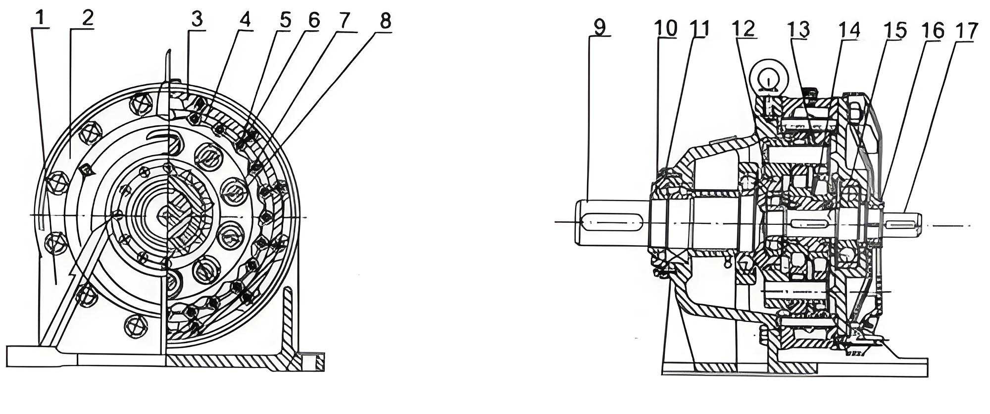
The descent regulator comprises four main subsystems: a manual rewinding mechanism, a cable drum, a减速机构 based on a cycloidal drive, and a hydraulic damping unit. The operational principle is designed to segment a long descent into multiple short phases, each approximately 0.8 to 1 meter in length. During descent, the weight of the user rotates the cable drum, which is connected through a one-way clutch to the input of the cycloidal drive. The cycloidal drive, functioning as a harmonic reducer, significantly reduces the rotational speed; specifically, after several rotations of the drum, the output shaft of the cycloidal drive completes one full revolution. This output shaft is integrated with a cam profile. During the cam’s rise phase, it depresses the piston of a hydraulic cylinder, engaging the damping system to decelerate the drum until motion stops. During the cam’s return phase, the piston retracts, allowing the drum to rotate freely for the next segment of descent. The hydraulic damping unit features a piston with a one-way valve and a damping orifice; fluid flow from the lower to upper chamber through the orifice creates resistance during deceleration, while reverse flow through the valve is unrestricted. A manual rewinding mechanism with a gear train allows quick cable retrieval, and additional one-way clutches prevent unwanted rotation during rewinding and isolate the减速机构 when not needed. This design ensures that the descent speed is automatically controlled without user intervention, adapting to varying loads through the mechanical properties of the cycloidal drive and hydraulic damping.
| Component | Function | Key Features |
|---|---|---|
| Manual Rewinding Mechanism | Enables quick cable retrieval after use or during setup. | Incorporates a 3:1 gear ratio and a one-way clutch to prevent back-driving. |
| Cable Drum | Stores the descent cable and translates linear descent into rotational motion. | Diameter varies from 63 mm (inner) to 102 mm (outer) to accommodate cable layering. |
| Cycloidal Drive (减速机构) | Provides high reduction ratio to transform drum rotation into cam motion. | Uses a cycloidal disc and pin gear arrangement; output cam controls damping engagement. |
| Hydraulic Damping Unit | Generates controlled resistance to decelerate the drum during cam rise phase. | Piston with one-way valve and damping orifice; fluid resistance governs deceleration rate. |
The cycloidal drive is the heart of this descent regulator, responsible for achieving the necessary speed reduction to enable segmented descent. A cycloidal drive, also known as a cycloidal speed reducer, operates on the principle of harmonic gearinG; it consists of an eccentric input shaft, a cycloidal disc (or rotor), and a ring of stationary pins (pin gear). As the input shaft rotates, the eccentric motion causes the cycloidal disc to undergo both planetary rotation and epicyclic motion relative to the pins, resulting in a high reduction ratio in a compact form. For this application, I designed the cycloidal drive to provide a reduction ratio that correlates with the desired descent segment length. Given an average cable drum circumference of approximately 263 mm (based on inner and outer diameters), and a target descent segment of about 1 meter, the required reduction ratio \( i \) is calculated as:
$$ i = \frac{\text{Descent Segment Length}}{\text{Average Drum Circumference}} = \frac{1000\ \text{mm}}{263\ \text{mm}} \approx 3.93 $$
To ensure robustness and simplify manufacturing, a reduction ratio of 4 was selected. In a cycloidal drive, the reduction ratio is determined by the number of pins on the stationary ring \( Z_p \) and the number of lobes on the cycloidal disc \( Z_c \), with the relationship given by:
$$ i = \frac{Z_p}{Z_p – Z_c} $$
For \( i = 4 \), I chose \( Z_p = 12 \) pins and \( Z_c = 9 \) lobes on the cycloidal disc. This configuration ensures smooth motion and high torque capacity. The geometry of the cycloidal disc tooth profile is critical for proper meshing and load distribution. The profile is derived from an epitrochoidal curve, and its parametric equations in Cartesian coordinates can be expressed as follows for the pin gear (stationary ring) and cycloidal disc, respectively:
For the pin gear profile (relative coordinates):
$$ X(t) = R \sin\left(\frac{t}{2Z_p}\right) – 2r \sin\left(\frac{t}{2}\right) \cos\left(\frac{t}{2} + \frac{t}{2Z_p}\right) $$
$$ Y(t) = R \cos\left(\frac{t}{2Z_p}\right) + 2r \sin\left(\frac{t}{2}\right) \sin\left(\frac{t}{2} + \frac{t}{2Z_p}\right) $$
For the cycloidal disc tooth profile:
$$ X(t) = R \sin\left(\frac{t}{2Z_c}\right) – 2r \sin\left(\frac{t}{2}\right) \cos\left(\frac{t}{2} – \frac{t}{2Z_c}\right) $$
$$ Y(t) = R \cos\left(\frac{t}{2Z_c}\right) – 2r \sin\left(\frac{t}{2}\right) \sin\left(\frac{t}{2} + \frac{t}{2Z_c}\right) $$
Here, \( R \) is the base circle radius of the cycloidal disc, \( r \) is the pin circle radius, \( Z_p \) and \( Z_c \) are as defined, and \( t \) is the parameter varying over \( 0 \) to \( 2\pi \). The base circle radius \( R \) is related to the pin circle radius by \( R = 2r Z_c \). With \( r = 15\ \text{mm} \), \( R = 2 \times 15 \times 9 = 270\ \text{mm} \). These equations were used to generate the tooth profiles in CAD software, ensuring accurate meshing. The output of the cycloidal drive is integrated with a cam profile on the pin gear’s external contour, which actuates the hydraulic piston. This integration minimizes space and parts count, enhancing reliability.
| Cycloidal Drive Parameter | Symbol | Value | Unit |
|---|---|---|---|
| Reduction Ratio | \( i \) | 4 | – |
| Number of Pin Gear Teeth | \( Z_p \) | 12 | – |
| Number of Cycloidal Disc Lobes | \( Z_c \) | 9 | – |
| Pin Circle Radius | \( r \) | 15 | mm |
| Base Circle Radius | \( R \) | 270 | mm |
| Cycloidal Disc Width | \( B \) | 20 | mm |
Strength analysis of the cycloidal drive components is essential to ensure durability under dynamic loads. The primary failure modes for cycloidal gears are surface pitting due to contact fatigue and tooth root bending fatigue. The contact between the cycloidal disc lobes and the pins can be approximated as Hertzian contact of two cylinders. The maximum contact stress \( \sigma_j \) at any meshing point is given by:
$$ \sigma_j = 0.0418 \sqrt[2]{\frac{P_i E_d}{B \rho_d}} \quad \text{(MPa)} $$
where \( P_i \) is the normal load at the contact point, \( E_d \) is the equivalent modulus of elasticity (for alloy steel, \( E_d = 200\ \text{GPa} \)), \( B \) is the face width of the cycloidal disc, and \( \rho_d \) is the equivalent curvature radius at the contact point. For bending strength, the tooth root stress \( \sigma_f \) is evaluated using a modified Lewis equation for gear teeth:
$$ \sigma_f = \frac{K F_t Y_{Fa} Y_{Sa}}{B m} \leq [\sigma_f] $$
Here, \( [\sigma_f] \) is the allowable bending stress, \( m \) is the module (which is larger than standard gears due to cycloidal geometry; empirically derived), \( K \) is the load factor (typically 1.98 for dynamic loads), \( F_t \) is the tangential force on the tooth, \( Y_{Fa} \) is the tooth form factor (approximately 2.44 for cycloidal profiles), and \( Y_{Sa} \) is the stress correction factor (approximately 1.65 for load application at the tooth tip). These calculations confirm that the designed cycloidal drive can withstand the expected operational stresses for loads up to 200 kg, which is the maximum design capacity.
To validate the structural integrity of the entire descent regulator, I conducted a finite element analysis (FEA) using ANSYS software. A three-dimensional geometric model was created in SolidWorks, focusing on key components like the cycloidal drive assembly, support plates, cable drum, and hydraulic cylinder. Minor features such as small fillets or chamfers were omitted to simplify meshing without compromising accuracy. The model was imported into HyperMesh for meshing, where tetrahedral Solid187 elements were employed. A refined mesh was applied to critical areas like the cycloidal disc teeth and piston contact regions to capture stress gradients effectively. The total mesh count was 863,242 elements. Material properties were assigned: for structural parts (base plate, side plates, drum, cycloidal components), alloy steel with Young’s modulus \( E = 206\ \text{GPa} \), Poisson’s ratio \( \mu = 0.3 \), and density \( \rho = 7.8 \times 10^3\ \text{kg/m}^3 \); for the hydraulic cylinder, aluminum alloy with \( E = 69\ \text{GPa} \), \( \mu = 0.33 \), and \( \rho = 2.9 \times 10^3\ \text{kg/m}^3 \). Boundary conditions fixed the base plate, and a static load equivalent to a 200 kg mass (approximately 1960 N force) was applied to simulate the maximum operating condition.
The FEA results provided insightful stress distributions. For the cycloidal drive, the maximum von Mises stress occurred at the contact points between the cycloidal disc lobes and the pins, with values around 107.5 MPa for the disc and 20.0 MPa for the pins, both well below the yield strength of alloy steel (typically > 400 MPa). This indicates that the contact stress is within safe limits, preventing pitting failure. The tooth root bending stresses were also analyzed, showing peaks below the allowable fatigue stress, ensuring resistance to crack initiation. The integration of the cycloidal drive with the cam profile did not induce significant stress concentrations, affirming the design’s robustness. For the support structure, the right side plate exhibited the highest stress at its base due to bending moments from the load, with a maximum stress of approximately 3.28 MPa, which is negligible compared to material strength. These findings guided minor reinforcements in high-stress areas, enhancing overall safety without adding bulk. The FEA confirms that the cycloidal drive为核心的减速机构 is not only functional but also structurally sound under extreme conditions.
Following the design and analysis phases, I fabricated a prototype of the descent regulator to experimentally verify its performance. The prototype was installed at a height of 6.5 meters (simulating a third-floor scenario), and tests were conducted with three different loads: 15 kg (dummy weight), 40 kg (dummy weight), and 64 kg (a human subject). The descent process was recorded, and parameters such as total descent time, segment length, and average speed were measured. The device operated as intended, producing a repeating cycle of descent (accelerating phase) followed by deceleration to a complete stop, with each segment consistently around 0.8 meters regardless of load. This consistency is attributed to the cycloidal drive’s fixed reduction ratio and the hydraulic damping’s fluid dynamics, which together regulate the segment length. The average descent speed increased slightly with load, due to higher forces driving the piston faster during the damping phase, but the variation was minimal, demonstrating good adaptability.
| Load (kg) | Total Descent Height (m) | Segment Length (m) | Total Time (s) | Average Speed (m/s) |
|---|---|---|---|---|
| 15 | 6.5 | 0.8 | 7.8 | 0.83 |
| 40 | 6.5 | 0.8 | 6.4 | 1.02 |
| 64 | 6.5 | 0.8 | 5.3 | 1.22 |
The experimental data underscores the device’s key advantages: automatic speed control without user adjustment, operational simplicity (the human subject required no prior training), and reliable performance across weights. The cycloidal drive played a crucial role in this by providing precise motion conversion, enabling the cam to actuate the damping system at the correct intervals. Compared to existing descent devices, this design eliminates the need for electronic controls or complex mechanisms, relying purely on mechanical principles embodied in the cycloidal drive and hydraulic damping. Potential improvements could focus on optimizing the cam profile for smoother transitions or using advanced materials to reduce weight, but the current prototype meets all design objectives.
In conclusion, the development of this novel descent control device demonstrates the effective application of cycloidal drive technology in emergency escape systems. By integrating a cycloidal drive with a hydraulic damper, I have created a mechanism that segments long descents into controlled, safe intervals, automatically adapting to user weight. The cycloidal drive provides high reduction ratio, compactness, and durability, making it ideal for this demanding application. Finite element analysis confirmed structural integrity, and prototype tests validated functional performance. This device offers a promising solution for high-rise building safety, combining simplicity, reliability, and ease of use. Future work may explore miniaturization for personal portable versions or integration with building infrastructure. Ultimately, the cycloidal drive proves to be a versatile and powerful component in mechanical design for life-saving equipment.
Throughout this project, the cycloidal drive has been central to achieving the desired motion control. Its ability to transform high-speed input into low-speed output with high torque capacity enabled the segmented descent approach. The cycloidal drive’s efficiency and robustness ensure that the device can withstand repeated use without significant wear, a critical factor for emergency equipment. Furthermore, the harmonic action of the cycloidal drive minimizes backlash and vibration, contributing to smooth operation. In essence, the success of this descent regulator hinges on the innovative use of cycloidal drive principles, showcasing how traditional mechanical elements can be adapted for modern safety challenges. As research continues, the cycloidal drive will likely find even broader applications in rescue and descent technologies, driven by its inherent advantages of precision, strength, and reliability.