
The pursuit of lower noise levels and enhanced transmission smoothness in automotive transmissions has led to the widespread adoption of complex gear geometries. Among these, small-sized gears with large helix angles present a significant challenge for the gear hobbing manufacturing process. In the past, the design of fixtures and the planning of the machining process for such gear hobbing operations relied heavily on the on-site experience of process engineers, lacking formal simulation or profiling programs. This experiential approach frequently resulted in unforeseen machining interferences during production. These interferences could manifest between the hob tool and the fixture, the hob head and the machine base, or the tool head and the machine worktable. Other common issues included collisions with pull rods or tailstocks and insufficient machine travel. The consequences ranged from minor production delays and line stoppages to the scrapping of parts, necessitating the costly and time-consuming re-manufacturing or repair of fixtures. Repaired fixtures often suffer from reduced stiffness, adversely affecting the stability and precision of the gear tooth profile. In severe cases, these interferences could lead to catastrophic machine tool damage or the destruction of expensive hob cutters.
To systematically eliminate these unpredictable and costly problems at the design stage, this project focuses on the research and development of a three-dimensional simulation technology specifically for interference prevention in gear hobbing. The core objective is to integrate this simulation into the actual design and production workflow, thereby enhancing production changeover efficiency, drastically reducing the on-site scrap rate, and improving overall machining quality and process reliability.
Core Research Content and Technological Innovation
The primary research was directed towards creating a virtual machining environment that accurately mirrors real-world gear hobbing conditions. The main tasks included:
- Compiling a comprehensive database of technical parameters for various gear hobbing machines, including axis travel limits and critical machine dimensions.
- Developing three-dimensional geometric models of these hobbing machines based on the collected data.
- Creating a simulation framework within specialized software to model the entire gear hobbing process, incorporating the machine, fixture, workpiece, and hob tool in a virtual 3D space.
The key innovation lies in the application of the VERICUT software platform to perform a dynamic, three-dimensional simulation of the gear hobbing process. This proactive approach allows for the identification and resolution of potential interferences and travel limit violations long before physical setup begins, effectively shifting problem-solving from the shop floor to the engineering office.
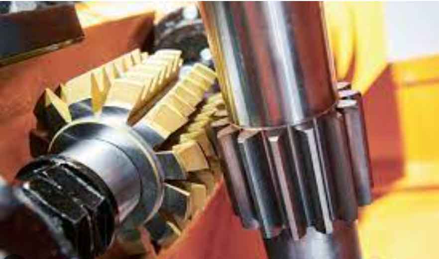
Simulation of the Gear Hobbing Process in a VERICUT Environment
VERICUT is a powerful CNC simulation and optimization software. However, it does not contain a native model for the gear hobbing process or an electronic gearbox function. Therefore, the process must be analytically modeled. The fundamental principle of gear hobbing is generating machining, where the rotating hob (representing a rack) and the rotating workpiece (the gear) maintain a strict kinematic relationship to cut the tooth profile.
To simulate this in VERICUT, the continuous generating motion is approximated using a multi-axis interpolation strategy, effectively converting it into a 6-axis, 4联动 CNC process. The six simulated axes are:
- Workpiece rotation (C-axis).
- Hob axial (Z-axis) feed motion.
- Hob radial (X-axis) in-feed motion.
- Hob rotation (B-axis).
- Hob head swivel (A-axis) for setting the installation angle.
- Hob head tangential (Y-axis) adjustment (for certain machines or setups).
This model enables a faithful simulation of the gear hobbing process for interference checking.
The overall workflow for building the simulation system is structured as follows:
| Step | Activity | Output |
|---|---|---|
| 1 | Machine Data Collection & 3D Modeling | Database of machine parameters; STL files of machine components. |
| 2 | Kinematic Model Definition | VERICUT component tree with correct kinematic chains. |
| 3 | Control System & Environment Setup | Configured machine in VERICUT with travel limits and collision checks. |
| 4 | Tool, Fixture, and Workpiece Setup | 3D models of all non-machine elements loaded into the simulation. |
| 5 | NC Program Generation | G-code simulating the generating motion and feed moves. |
| 6 | Process Simulation & Analysis | Visualization of the machining process and collision/over-travel reports. |
1. Geometric Modeling of the Hobbing Machine
The first step involves creating accurate 3D solid models of the gear hobbing machine. Critical dimensions and travel limits for all axes are meticulously measured and recorded to form a foundational database. Using CAD software like Siemens NX, individual components are modeled, including:
- Machine bed and column
- Workpiece spindle headstock (C-axis)
- Tailstock unit
- Hob slide (X-axis)
- Hob carriage axial slide (Z-axis)
- Hob head swivel assembly (A-axis)
- Hob head tangential slide (Y-axis – if applicable)
- Hob arbor and drive (B-axis)
Subsequently, the fixture, gear blank (stock), and the hob cutter itself are modeled. All components are then assembled in their correct relative positions to create a complete digital twin of the machine setup. The entire assembly is exported component-by-component into STL format, a standard format readable by VERICUT.
2. Kinematic Modeling and Machine Configuration in VERICUT
Within VERICUT, a machine component tree is constructed to define the kinematic relationships. The gear hobbing machine’s motion can be described by two main kinematic chains plus an auxiliary motion:
| Chain | Kinematic Sequence (Base to Tool/Workpiece) |
|---|---|
| Tool Chain | Base (Machine Bed) → X-Axis → Z-Axis → A-Axis → Y-Axis → B-Axis → Hob Cutter |
| Workpiece Chain | Base (Machine Bed) → C-Axis → Fixture → Stock → Workpiece |
| Auxiliary | Base (Machine Bed) → Tailstock |
The previously exported STL files are attached to their corresponding components in the tree. The machine coordinate system is typically set at the center of the workpiece face. A control system appropriate for multi-axis interpolation is selected and configured. Creating an accurate tool model is critical. The hob’s STL geometry is imported, and its cutting profile (number of starts, module, etc.) is defined within VERICUT’s tool library to enable material removal simulation.
3. Programming the Simulated Hobbing Motion
Since VERICUT lacks a built-in electronic gearbox, the generating motion must be replicated through G-code programming. This involves creating a program that synchronizes the B-axis and C-axis rotations according to the fundamental gear hobbing ratio, while coordinating the linear feeds. The core mathematical relationship governing the generating motion is:
$$ \frac{\omega_{hob}}{\omega_{workpiece}} = \frac{Z_{gear}}{Z_{hob\_starts}} $$
Where:
- $\omega_{hob}$ is the rotational speed of the hob (B-axis).
- $\omega_{workpiece}$ is the rotational speed of the workpiece (C-axis).
- $Z_{gear}$ is the number of teeth on the gear being cut.
- $Z_{hob\_starts}$ is the number of starts on the hob cutter.
This ratio is maintained via precisely calculated simultaneous moves in the NC program.
Other critical programming considerations include:
- Hob Installation Angle (A-axis): The hob must be swiveled to an angle ($\alpha$) relative to the gear axis to match the gear’s helix angle ($\beta$) and the hob’s lead angle ($\gamma$). The rule is “Opposite angles subtract, same angles add”:
$$ \alpha = \beta \mp \gamma $$
(Minus sign for same hand of helix, plus sign for opposite hand). - Infeed and Retract Strategy: The simulation must include the non-cutting movements: the radial (X-axis) approach to the full cutting depth, the axial (Z-axis) feed along the gear face, and the safe retraction of the hob after machining.
- Hob Shifting (Cutter Overlap Management): To distribute wear evenly along the hob’s length, it is shifted axially after machining each gear or a batch of gears. The usable length of the hob for simulation purposes is less than its total length. A safe margin (L) from the workpiece center to the hob end must be maintained, typically at least 1.5 times the gear’s circular pitch.
$$ \text{Usable Hob Length} = L_{total} – 2 \cdot L_{holder} – 2 \cdot L $$
$$ \text{where } L \ge 1.5 \times p_c \text{ and } p_c = \pi m_n $$
($p_c$ is circular pitch, $m_n$ is normal module).
4. Configuring the Simulation Environment for Robust Checking
To make the simulation an effective preventive tool, the virtual environment is configured with strict checks:
| Check Type | Configuration Setting | Purpose |
|---|---|---|
| Collision Detection | Enable checks between: Hob vs. Fixture, Hob vs. Tailstock, Hob Head vs. Machine structure. | To visually and programmatically flag any physical interference during simulation, typically highlighted in red. |
| Travel Limit Control | Set positive and negative soft limits for all linear and rotary axes (X, Z, Y, A, C) based on the machine database. | To stop the simulation and issue a warning if any axis movement exceeds the machine’s physical capabilities. |
| Motion Priority | Define the sequence of operations: 1. Clamp/Unclamp (tailstock), 2. Engage A-axis angle, 3. Start B & C axis rotation, 4. Execute linear feeds (X, Z, Y). | To mimic the safe operational sequence of a real hobbing machine. |
Execution and Benefits of the 3D Simulation
With the machine modeled, the environment configured, and the NC program loaded, the gear hobbing process is simulated in full. The simulation runs through the entire sequence: machine preparation, tailstock advance and clamping, hob infeed, the generating cut along the gear face, hob retraction, and unclamping. Throughout this dynamic visualization, the system actively monitors for the predefined collision and travel limit conditions.
The application of this 3D simulation technology provides transformative benefits for manufacturing, particularly for challenging components like small gears with large helix angles. It fundamentally changes the process planning paradigm by:
- Eliminating Design-Phase Uncertainties: Potential interference problems are identified and resolved during the initial fixture and process design, preventing costly errors on the shop floor.
- Optimizing Fixture and Tooling Design: Designers can iterate virtually, ensuring optimal clearance and stiffness from the outset, leading to better gear quality.
- Reducing Machine Setup Time and Scrap: First-time-right setups become the norm, significantly reducing non-productive time and the risk of scrapped components.
- Protecting Capital Equipment: The risk of catastrophic machine tool crashes or damage to expensive hob cutters is virtually eliminated.
- Enhancing Knowledge Capture: The simulation model and database serve as a reusable, standardized knowledge base, reducing dependency on individual operator experience.
In conclusion, the development and integration of a VERICUT-based 3D anti-interference simulation system for gear hobbing represents a significant advancement in manufacturing process security and efficiency. By creating a high-fidelity virtual prototype of the entire machining system, it allows engineers to proactively validate and optimize the gear hobbing process, ensuring robustness, quality, and safety before any physical metal is cut. This technology is especially indispensable for the reliable and efficient production of complex gear geometries that are essential for modern, high-performance automotive transmissions.