
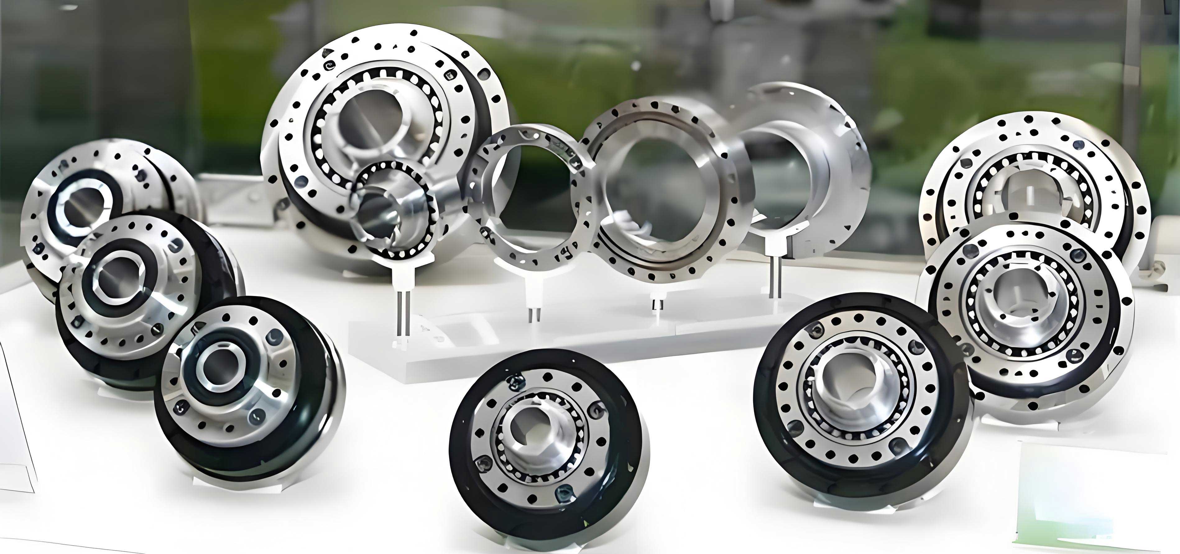
In my experience with engineering machinery, particularly hydraulic excavators, the travel drive system is foundational to machine mobility. This system is powered by a pair of travel motors. These motors are not simple hydraulic units; they are highly integrated, compact drive assemblies that combine a hydraulic motor, a rotary vector reducer, integrated hydraulic valves, and a parking brake mechanism. The heart of this assembly, and the focus of our development efforts, is the RV reduction gear. Its compact design, which incorporates a planetary gear stage coupled with a cycloidal pin gear stage, offers exceptional impact resistance, high rotational precision, a large reduction ratio, and a long service life.
Despite their widespread adoption in the domestic excavator industry and expanding applications in other machinery, reliable, high-performance rotary vector reducers were not available from local manufacturers and were primarily imported. This dependency highlighted a critical gap in our domestic supply chain. Therefore, leveraging the technical expertise available within our company, we undertook a project to develop and localize the production of this key component. The successful development of a domestic rotary vector reducer holds significant practical importance for the independent growth of our engineering machinery sector.
1. Core Specifications and Operational Principles
The primary technical parameters set for our rotary vector reducer were defined based on the operational demands of medium-to-large hydraulic excavators:
| Parameter | Specification |
|---|---|
| Operating Temperature | -10°C to +45°C |
| Maximum Output Torque | 34,300 N·m |
| Maximum Output Speed | 60 rpm |
| Reduction Ratio | 44.87 |
| Braking Torque | 398 N·m |
The fundamental mission of the rotary vector reducer is to convert the high-speed, low-torque rotation from the hydraulic motor into the low-speed, high-torque output required to drive the sprocket and, consequently, the track chain. This transformation is achieved through a unique two-stage closed planetary system.
The first stage is a standard involute planetary gear reduction. The sun gear, driven by the motor, engages with multiple planetary gears housed within a planetary carrier. The second stage is the distinctive cycloidal or RV stage. The planetary carrier from the first stage drives multiple crankshafts. Each crankshaft has an eccentric section that engages with a cycloidal disc via a bearing. Typically, two cycloidal discs, phase-shifted by 180°, are used. These discs mesh with a ring of stationary pin gears (mounted on the housing) or output pin gears (mounted on the output member). As the crankshafts rotate, they cause a controlled eccentric motion in the cycloidal discs. Because the discs have lobes that engage with the pins, this eccentric motion is translated into a slow, reverse rotation of the discs themselves. This rotation is then extracted by an output mechanism (often a pin or a flange) connected to the output shaft or sprocket hub.
The kinematic relationship defining the reduction ratio $i_{RV}$ of a standard rotary vector reducer can be expressed as:
$$ i_{RV} = 1 + \frac{Z_p}{Z_c} $$
where $Z_p$ is the number of pins in the ring and $Z_c$ is the number of lobes on the cycloidal disc. In a two-stage RV reducer like ours, the total ratio $i_{total}$ is the product of the first-stage planetary ratio $i_{planetary}$ and the cycloidal stage ratio $i_{RV}$:
$$ i_{total} = i_{planetary} \times i_{RV} = (1 + \frac{Z_r}{Z_s}) \times (1 + \frac{Z_p}{Z_c}) $$
where $Z_r$ is the number of teeth on the ring gear and $Z_s$ is the number of teeth on the sun gear in the first stage.
2. Structural Advantages and Design Philosophy
From a design and application standpoint, the rotary vector reducer architecture offers several compelling advantages that guided our development process:
- High Compactness and Stiffness: The entire transmission is nested within the supporting structure, minimizing axial dimensions. The output is supported by a large, rigid flange (the sprocket hub), providing tremendous torsional stiffness compared to cantilevered output designs. The cycloidal meshing involves multiple tooth contacts simultaneously, and pins are often supported as “half-buried” posts, leading to very high contact rigidity and outstanding shock load resistance.
- High Precision and Low Backlash: With careful design, precision manufacturing, and controlled assembly, the rotary vector reducer can achieve remarkably high positional accuracy and minimal backlash. This is critical for smooth and controlled travel motion in excavators.
- High Reduction Ratio and Efficiency: The design inherently provides a very high reduction ratio in a single package. By varying the tooth counts in the first planetary stage while keeping the cycloidal stage constant, a range of ratios can be efficiently achieved. The transmission efficiency is also high, typically ranging between 85% and 92%.
- Excellent Load Distribution and Long Life: The use of multiple crankshafts and planet gears distributes the load evenly. The low relative speed at the crankshaft bearings (needle roller bearings) and the high number of contact points in the cycloidal mesh contribute to exceptional durability and service life.
3. Critical Technologies and Manufacturing Challenges
The performance of the rotary vector reducer is exquisitely sensitive to the precision of its key components. Our development focused intensely on the design, material selection, heat treatment, and machining of these parts.
3.1 Cycloidal Disc (RV Gear) Design and Fabrication
The cycloidal disc is a thin, disc-like component featuring bearing holes for the crankshaft eccentrics, lightening/assembly holes, and the precise external cycloidal tooth profile. Post carburizing and quenching, it possesses a deep, hard case but is prone to distortion.
The paramount requirement is the relative positional accuracy of the three bearing holes within a single disc and between the paired discs, rather than their absolute positional accuracy against an external datum. This “equal-direction distribution of link length error” is crucial for minimizing kinematic error. Our manufacturing sequence was engineered accordingly:
- First, machine the three bearing holes in the rough-machined disc.
- Use these holes as the primary datum to finish-machine the cycloidal tooth profile on a CNC form grinding machine, ensuring control over adjacent pitch error and cumulative pitch error.
- Machine the corresponding holes in the planetary carrier using the same datum system, guaranteeing congruence.
- Process discs in matched pairs, marking them for assembly.
Tooth profile modification, essential for proper lubrication and load distribution, was achieved using a combination of negative equidistant and negative profile shift methods. Final inspection of the finished discs confirmed compliance with all design tolerances.
3.2 Crankshaft Precision Manufacturing
The crankshaft is a complex shaft integrating journal bearings, eccentric throws, and an involute spline. Its critical tolerances include eccentricity value, parallelism of eccentric sections, coaxiality of journals, and the angular relationship between the spline and the adjacent eccentric throw.
Our key challenges and solutions were:
- Heat Treatment Distortion: A systematic heat treatment process involving deep cryogenic treatment was developed to control retained austenite to ≤1%, ensuring dimensional stability throughout the component’s life and enhancing core hardness and fatigue strength.
- Phase and Orientation Control: The requirement that eccentric throws on the same end be 180° apart within ±1 arc-minute, and that the spline tooth space align with the low point of the adjacent eccentric throw within ±1 arc-minute, demanded extreme precision. We utilized an imported specialized crankshaft grinder. After grinding the spline, the shaft was mounted between centers. A dedicated fixture, using a precision ball seated in the spline space for angular定位, allowed for the simultaneous finish-grinding of both eccentric throws and the main journals in a single setup, guaranteeing phase accuracy and orientation.
3.3 Sprocket Hub (Output Carrier) and Surface Engineering
The sprocket hub is a large, thin-walled casting that serves as the output carrier. It houses the ring of pin gears and supports the main output bearings. Machining the array of semi-circular pin bores to high precision was a significant hurdle.
Our process innovation involved machining the pin holes as full circles in the casting, then using wire-cut EDM to precisely slice them into the required semi-circular profile. This approach avoided the vibration and tool deflection associated with machining semi-circles directly, ensuring excellent bore roundness, perpendicularity, positional accuracy, and surface finish.
A pivotal technology we implemented was the application of a solid lubricant coating on the pin bore surfaces. We selected an ion-plated composite coating of Molybdenum Disulfide (MoS₂) and Antimony Trioxide (Sb₂O₃), with a thickness of 15–20 μm. Pretreatment ensured strong adhesion. MoS₂ provides an exceptionally low coefficient of friction and high load-bearing capacity. However, its weakness is oxidation at elevated temperatures. The addition of Sb₂O₃ significantly improves the coating’s oxidation resistance and acts as a synergistic agent, enhancing the overall anti-friction and anti-wear performance of the coating within the rotary vector reducer.
4. Assembly, Testing, and Validation
To rigorously validate our domestically produced rotary vector reducer, we designed a comparative assembly and testing protocol against an imported benchmark unit.
4.1 Test Methodology
- Baseline Test A: Assemble and conduct a no-load type test on the complete imported reducer.
- Baseline Test B: Assemble and conduct a no-load type test on our complete domestically produced reducer.
- Hybrid Test C: Assemble a unit using the imported RV core assembly (crankshafts, cycloidal discs, pins) with our domestic housing, bearings, and seals. Perform the no-load test.
- Hybrid Test D: Assemble a unit using our domestic RV core assembly with the imported peripheral components. Perform the no-load test.
The no-load test, performed on a dedicated hydraulic test bench at operational speeds, assessed bearing lubrication, seal integrity, temperature rise, and noise levels.
4.2 Results and Analysis
All four configurations operated smoothly, with normal noise levels, reliable sealing, and good lubrication. The key metric, bearing temperature rise over time, provided the most direct comparison of internal efficiency and friction. The temperature-time curves for the hybrid tests and the baseline tests were analyzed.
| Test Configuration | Key Observation | Conclusion |
|---|---|---|
| Imported Reducer (Baseline A) | Established reference temperature profile. | Performance benchmark. |
| Domestic Reducer (Baseline B) | Temperature profile nearly identical to Baseline A. | Domestic unit’s performance matches the import. |
| Hybrid C (Import Core + Domestic Peripheral) | Temperature profile consistent with benchmarks. | Our housing, bearing fits, and seals are compatible and perform correctly. |
| Hybrid D (Domestic Core + Import Peripheral) | Temperature profile consistent with benchmarks. | Our core RV assembly (crankshafts, discs, pins) generates comparable friction and heat to the import. |
The near-superposition of the temperature curves, particularly between the fully domestic unit and the imported benchmark, was a strong indicator of success. It demonstrated that our manufacturing processes for the critical components resulted in comparable meshing friction, bearing preload, and overall mechanical efficiency.
4.3 Field Application
Following successful bench testing, two prototype units integrating our domestic rotary vector reducer were installed on hydraulic excavators for field evaluation. The machines have been in operation for an extended period, and the reducers have performed reliably without any functional anomalies, fully meeting the requirements of the excavator’s travel system.
5. Conclusion
Through this development project, we have successfully localized the manufacture of a key component for hydraulic excavators: the travel motor rotary vector reducer. The process involved a deep dive into the error sensitivity analysis of the RV mechanism, which directly informed our advanced manufacturing strategies for the cycloidal discs, crankshafts, and sprocket hub. The implementation of specialized fixtures, precise grinding techniques, controlled heat treatment sequences, and innovative surface coatings like MoS₂+Sb₂O₃ were critical to achieving the necessary component quality.
Rigorous comparative testing confirmed that the performance of our domestically produced rotary vector reducer is on par with that of imported units, exhibiting smooth operation, proper temperature characteristics, and reliable sealing. The subsequent successful field application validates the design, manufacturing, and assembly processes. This achievement marks a significant step toward supply chain independence in the domestic engineering machinery industry and provides a solid foundation for applying this high-performance reduction technology to a broader range of mechanical applications.