
Currently, most gear forging enterprises face the dual pressures of rising labor costs and recruitment difficulties. Traditional manual forging production lines are becoming increasingly unsustainable. For forging enterprises to offer competitive products in the future, considering both quality and cost perspectives, the transition to automated forging production is an inevitable trend. This article details our first-hand experience in developing and overcoming challenges within an automated production line dedicated to the warm precision forging of straight bevel gear blanks, specifically for automotive differential applications.
The straight bevel gears discussed are manufactured from low-carbon alloy steel. Warm forging is conducted within a precise temperature range of 800–850°C. This process achieves near-net shape forming of the gear teeth, approaching the precision typically associated with cold forging. Crucially, compared to cold forging, it eliminates the need for blank annealing and phosphating/soaping lubrication pre-treatments. This streamlines the production cycle by 3-4 days, aligning perfectly with green manufacturing principles. The core objective was to establish a highly efficient, reliable, and cost-effective automated line for producing high-quality forged gear blanks.
1 Gear Forging Process and Production Line Layout
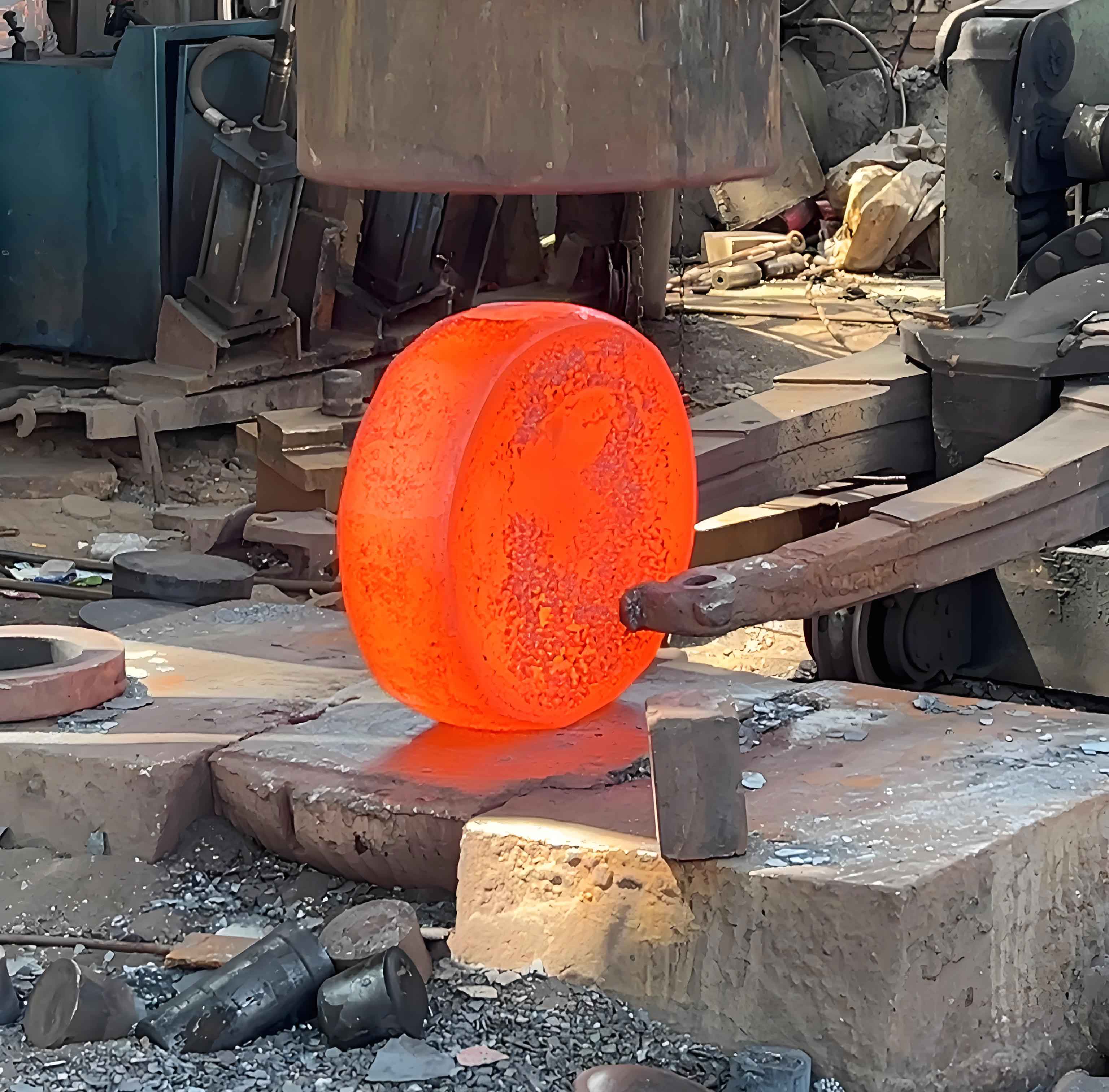
The chosen process for the straight bevel gear blank involves closed-die forging without flash, achieving final form through a single-heat, two-stage operation (pre-forging followed by final forging). The final forged gear blank geometry is illustrated below.
The automated production line layout integrates several key components:
- 2 x 630-ton Electric Screw Presses
- Automatic Feeding System
- Medium Frequency (MF) Induction Heating Furnace
- 3 x Industrial Robots
- Graphite Spraying System
The complete production workflow is:
- Bar Cutting
- Facing & Chamfering
- Initial Heating
- Pre-coating with Graphite
- Final Heating
- Pre-forging
- Final Forging
- Controlled Cooling
- Shot Blasting
- Machining
- Heat Treatment
- Finish Machining
- Cleaning & Packaging
The pre-coating graphite step is vital. It significantly reduces surface oxidation and decarburization during subsequent heating and forging, thereby enhancing the surface quality of the final forged gear blank. Precise temperature control within the MF furnace and consistent forging rhythm are critical factors influencing the microstructure and dimensional stability of the forged gear blank. The relationship between forging force \( F \), material flow stress \( \sigma_f \), and the projected contact area \( A \) during deformation can be approximated by:
$$ F = k \cdot \sigma_f \cdot A $$
where \( k \) is a factor accounting for die friction and shape complexity. Maintaining stable parameters minimizes variability in the forged gear blank.
The benefits of automation over traditional manual lines for this forged gear blank are substantial, as summarized below:
| Factor | Manual Line | Automated Line |
|---|---|---|
| Manpower Required | 6-8 operators | Max. 2 operators |
| Operator Labor Intensity | High (Manual handling of hot blanks) | Low (Robotic handling) |
| Working Environment | Harsh (Heat, noise, potential hazards) | Significantly Improved |
| Process Consistency & Blank Quality | Variable (Subject to human factors) | Highly Stable (Reduced variability) |
| Productivity vs. Machining | N/A (Baseline) | Increase ~200x |
| Material Utilization | N/A (Baseline) | Increase ~40% |
| Batch Production Cost | N/A (Baseline) | Reduction ~30% |
2 Continuous Improvement of the Gear Forging Production Line
Implementing the automated line presented several technical challenges requiring targeted solutions to ensure consistent production of high-quality forged gear blanks:
2.1 Ensuring Consistent Blank Ejection for Robotic Pickup
A critical issue involved part ejection. Conventional hydraulic top knockout systems exhibit inherent “hydraulic lag.” This meant the forged blank often did not separate cleanly from the upper die until the press slide had retracted significantly. Consequently, the blank might not reliably remain in the lower die for the robot to pick up. This led to two failure modes:
- The robot gripper misses the blank entirely, causing line stoppage.
- The robot grips the blank partially or inaccurately, leading to misalignment (“tooth shifting”) during the next forging stage, scrapping the forged gear blank.
Solution: We replaced the hydraulic system with an elastic energy storage top knockout mechanism utilizing high-pressure nitrogen gas springs. This modification ensures immediate and consistent ejection upon slide retraction, guaranteeing the forged gear blank remains correctly positioned in the lower die for reliable robotic pickup. The force \( F_{ko} \) delivered by such a system can be modeled based on the initial gas pressure \( P_0 \), volume \( V_0 \), and the knockout stroke \( s \):
$$ F_{ko} = P_0 \cdot A_p \cdot \left( \frac{V_0}{V_0 – A_p \cdot s} \right)^\gamma $$
where \( A_p \) is the piston area and \( \gamma \) is the gas constant (approximately 1.4 for N₂). This ensures sufficient force is available throughout the ejection stroke.
2.2 Mitigating Blank Eccentricity
Initial production runs revealed excessive unilateral eccentricity (misalignment) in the forged gear blank, ranging from 0.4mm to 0.5mm. This posed a serious risk of insufficient machining allowance on one side of the blank. Root cause analysis identified two primary contributors:
- Material anisotropy causing non-uniform flow.
- Inconsistent lubrication conditions.
- Insufficient rigidity and effective guide length in the die guiding system, allowing lateral shift before significant deformation occurred.
Solution: The die guiding system was redesigned to significantly increase the effective guide engagement length prior to material deformation. Ensuring an effective guide length \( L_{eff} \) greater than 5mm before substantial metal flow occurs drastically reduced lateral forces acting on the dies. This improvement successfully controlled the eccentricity of the forged gear blank to within 0.15mm. The critical buckling load \( P_{cr} \) for the guide pillars is a key design parameter:
$$ P_{cr} = \frac{\pi^2 \cdot E \cdot I}{(K \cdot L)^2} $$
where \( E \) is Young’s modulus, \( I \) is the moment of inertia of the pillar cross-section, \( L \) is the unsupported length, and \( K \) is the effective length factor (dependent on end conditions). Ensuring \( P_{cr} \) far exceeds the anticipated lateral forging loads is essential.
2.3 Preventing Rotational Shift of Tooth Dies
Vibration inherent in the forging process caused the pre-forge and final forge tooth dies to loosen slightly within their pockets. This resulted in an undesired rotational shift of the tooth profiles relative to each other. Consequently, the pre-forged blank would be misaligned (“tooth shifted”) when placed into the final forge die, causing catastrophic mis-forging and scrapping the forged gear blank.
Solution: Robust positive location was implemented by machining precision keyways into both the die inserts and the die holder pockets. Matching keys were fitted. This physically prevents any rotational movement of the dies once clamped, ensuring perfect angular alignment between the pre-forge and final forge tooth profiles for every forged gear blank.
2.4 Extending Low Die Life
Initial die life for the critical tooth-forming inserts, especially in the high-wear final forging stage, was unacceptably low at approximately 10,000 pieces per set. Frequent die changes disrupted production flow and increased costs per forged gear blank.
Solution: We collaborated with material science partners to implement advanced Physical Vapor Deposition (PVD) coatings onto the die working surfaces. Specific coatings like AlCrN or TiAlN were optimized for high-temperature wear resistance and anti-galling properties against the hot steel forged gear blank. This surface engineering intervention dramatically increased die life by a factor of 2.8-3.0, reaching 28,000-30,000 pieces per set. The wear rate \( W \) of coated vs. uncoated dies can be expressed using an Archard-like equation:
$$ W = k \cdot \frac{H}{F_n \cdot v \cdot s} $$
where \( k \) is a wear coefficient (significantly lower for PVD coated dies), \( H \) is hardness, \( F_n \) is normal load, \( v \) is sliding velocity, and \( s \) is sliding distance. The coating effectively reduces the wear coefficient \( k \). This technology is now standard practice.
2.5 Reducing Complex Die Setup Time
Following die changes, aligning the pre-forge and final forge tooth profiles angularly was a complex, time-consuming manual process, typically requiring 120 minutes. This downtime significantly impacted overall line productivity and the cost per forged gear blank.
Solution: Building upon the keying solution for rotation prevention (2.3), precision machining datums were incorporated onto the die inserts themselves. Combined with the keyways, this allows new dies to be loaded into their respective pockets and securely clamped. The positive location ensures immediate, correct angular alignment between the pre-forge and final forge tooth profiles without any manual adjustment. This innovation slashed die setup time to under 40 minutes, enabling true Single Minute Exchange of Die (SMED) principles for these critical tools.
| Challenge | Impact | Solution | Key Outcome |
|---|---|---|---|
| Inconsistent Blank Ejection | Robot pickup failures, scrapped blanks | Nitrogen Spring Top Knockout | Reliable robotic pickup, zero mis-picks |
| Blank Eccentricity (0.4-0.5mm) | Risk of insufficient machining stock | Increased Die Guide Engagement (>5mm) | Eccentricity < 0.15mm |
| Rotational Die Shift | Tooth misalignment, scrapped blanks | Precision Keyways in Dies & Holders | Eliminated angular misalignment |
| Low Die Life (~10,000 pieces) | High cost, frequent downtime | Advanced PVD Coating Application | Die Life 28,000-30,000 pieces |
| Long Die Setup (120 min) | Low Overall Equipment Effectiveness (OEE) | Integrated Datums & Keying for SMED | Setup Time < 40 min |
These continuous improvements were driven by rigorous data collection and analysis. Statistical Process Control (SPC) charts were implemented for critical forged gear blank dimensions (e.g., crown thickness, bore diameter, tooth profile runout). Process capability indices (Cp, Cpk) were tracked before and after each improvement to quantify the impact on quality consistency. The reduction in process variability directly enhanced the Cp/Cpk values for key characteristics of the forged gear blank.
| Metric | Performance | Impact |
|---|---|---|
| Labor Reduction | >75% (8 -> 2 operators) | Major reduction in labor cost per blank |
| Scrap Rate Reduction | ~45% (Mainly from solved issues 2.1, 2.2, 2.3) | Lower material cost, higher yield |
| OEE Increase | ~35% (Combined effect of solutions 2.1, 2.4, 2.5) | Higher output volume, lower fixed cost per blank |
| Die Cost per Blank | ~65% Reduction (Due to 2.4) | Significant cost savings |
| Overall Cost per Blank | ~30% Reduction | Enhanced market competitiveness |
3 Conclusion
The successful development and continuous refinement of this automated warm precision forging line for straight bevel gear blanks represent a significant technological advancement. By systematically addressing critical challenges – ensuring reliable robot interaction, enhancing dimensional accuracy through improved die guidance, eliminating rotational misalignment, drastically extending die life via PVD coatings, and implementing SMED for dies – we achieved a robust and highly efficient manufacturing system. The result is the consistent production of high-quality forged gear blanks characterized by excellent dimensional stability, surface integrity, and material properties.
The tangible benefits are substantial: a drastic reduction in manual labor (>75%), significantly improved operator working conditions, a ~30% reduction in overall manufacturing cost per forged gear blank, and a major increase in productivity and process stability. The elimination of annealing and phosphating/soaping steps inherent in the warm forging process provides a clear environmental advantage, reducing energy consumption and hazardous chemical usage.
This project demonstrates the viability and substantial benefits of automation integrated with advanced process and tooling technologies for complex forged gear blank production. The knowledge gained and solutions implemented offer a valuable blueprint for the forging industry, paving the way for wider adoption of automated precision forging. The resulting increase in competitiveness, combined with the environmental benefits, underscores the significant social and economic value of this automated production line for manufacturing high-performance forged gear blanks.