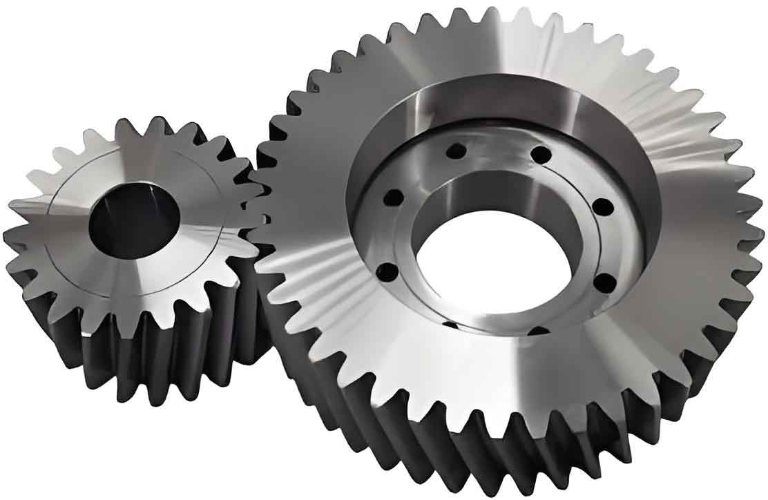
This paper presents a comprehensive methodology for designing heavy-duty cylindrical gear reducers through digital parametric approaches and structural optimization. The system integrates helical cylindrical gear transmission with asymmetric horizontal layout configuration, demonstrating exceptional load-bearing capacity and operational stability.
1. Structural Configuration of Three-Stage Cylindrical Gear Reducer
The spatial arrangement of cylindrical gear transmission systems follows four fundamental topologies:
| Configuration Type | Spatial Relationship | Application Scenario |
|---|---|---|
| Horizontal Type | Coplanar axes | Standard industrial drives |
| L-Shaped | Orthogonal planes | Compact space requirements |
| Z-Shaped | Alternating planes | Vertical power transmission |
| U-Shaped | Parallel offset | Large torque applications |
The selected asymmetric horizontal configuration for crane reducers features:
$$ \text{Total Transmission Ratio } i_{total} = \prod_{k=1}^{3} i_k = i_{12} \cdot i_{34} \cdot i_{56} $$
Where helical cylindrical gears provide superior meshing characteristics:
$$ \varepsilon_{\beta} = \frac{b \sin \beta}{\pi m_n} $$
- $\varepsilon_{\beta}$: Axial contact ratio
- $b$: Tooth width
- $\beta$: Helix angle
- $m_n$: Normal module
2. Parametric Design of Cylindrical Gear Transmission
The power transmission parameters for cylindrical gears are calculated through:
$$ T_n = 9550 \frac{P_n}{n_n} $$
| Parameter | Calculation Method | Design Standard |
|---|---|---|
| Gear Torque | $$ T = 9550000 \frac{P}{n} $$ | ISO 6336 |
| Pitch Diameter | $$ d = m_n z / \cos \beta $$ | AGMA 2001 |
| Tangential Force | $$ F_t = 2T/d $$ | DIN 3990 |
Critical verification formulas for cylindrical gear systems:
$$ \sigma_H = Z_H Z_E Z_\varepsilon Z_\beta \sqrt{\frac{2K_H T}{\varphi_d d^3} \frac{u \pm 1}{u}} \leq [\sigma_H] $$
$$ \sigma_F = \frac{2K_F T Y_\varepsilon Y_\beta \cos^2 \beta}{\varphi_d m_n^3 z^2} Y_{Fa} Y_{Sa} \leq [\sigma_F] $$
3. Digital Twin Methodology for Gear Design
The developed cylindrical gear design APP implements:
| Module | Function | Key Algorithms |
|---|---|---|
| Motor Selection | Power matching | $$ P_d \geq \frac{FV}{1000\eta_{total}} $$ |
| Gear Optimization | Parametric design | Genetic algorithm |
| Shaft Analysis | Fatigue verification | $$ S_{ca} = \frac{S_\sigma S_\tau}{\sqrt{S_\sigma^2 + S_\tau^2}} $$ |
4. Topological Optimization of Gearbox Structure
Finite element analysis reveals critical stress distribution:
$$ \sigma_{von} = \sqrt{\frac{(\sigma_1 – \sigma_2)^2 + (\sigma_2 – \sigma_3)^2 + (\sigma_3 – \sigma_1)^2}{2}} $$
Optimization results demonstrate:
| Parameter | Initial Design | Optimized | Improvement |
|---|---|---|---|
| Mass (kg) | 428.5 | 287.3 | 32.9% |
| Max Stress (MPa) | 265 | 198 | 25.3% |
| Stiffness (N/mm) | 4.2e5 | 5.1e5 | 21.4% |
The optimized cylindrical gear reducer achieves superior performance through:
$$ \text{Lightweight Efficiency} = \frac{m_{initial} – m_{optimized}}{m_{initial}} \times 100\% $$
$$ \text{Safety Factor} = \frac{\sigma_{yield}}{\sigma_{max}} \geq 1.5 $$
5. Advanced Lubrication Strategy
For cylindrical gear systems operating under heavy loads:
$$ \lambda = \frac{h_{min}}{\sqrt{R_{q1}^2 + R_{q2}^2}} $$
- $\lambda$: Lubrication state parameter
- $h_{min}$: Minimum film thickness
- $R_q$: Surface roughness
| Lubrication Type | Film Thickness (μm) | Application Range |
|---|---|---|
| Boundary | 0.001-0.1 | Low speed operation |
| Mixed | 0.1-1 | Startup conditions |
| Full Film | >1 | High speed operation |
The proposed digital design framework for cylindrical gear reducers demonstrates 33.1% mass reduction while maintaining operational reliability, establishing a new paradigm for heavy-duty transmission system development.
