
As a precision transmission device widely adopted in industrial robotics, particularly for heavy-duty joints such as the base, arm, and shoulder, the rotary vector reducer has garnered significant attention due to its outstanding performance characteristics. My focus in this analysis is to delve into the intricate digital modeling and structural assembly process of this reducer. The compact structure, high reduction ratio, low vibration, and minimal noise output of the rotary vector reducer make it an indispensable component in modern automation. Constructing an accurate three-dimensional digital prototype is a foundational and critical step for subsequent in-depth research, including finite element analysis for strength verification, transient dynamics simulation, contact stress evaluation, and transmission error prediction. This process provides the essential digital model that enables virtual testing and optimization before physical prototyping.
Structural Analysis and Operational Principle
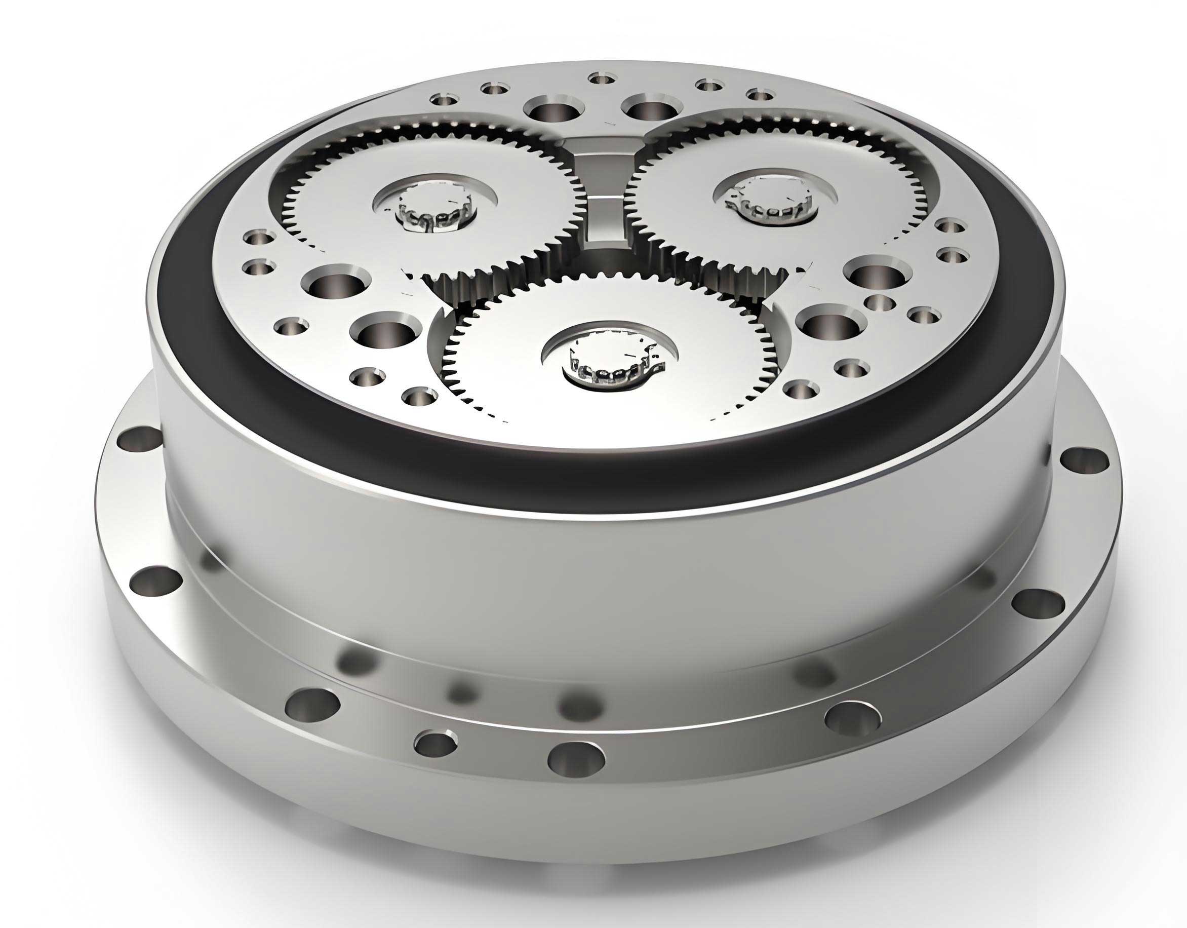
The rotary vector reducer achieves its high reduction ratio through a two-stage hybrid transmission system. This design cleverly combines a first-stage planetary gear train with a second-stage cycloidal pin-wheel mechanism. Understanding this architecture is paramount for accurate modeling.
The first stage is a conventional involute planetary gear set. It consists of a central sun gear, typically three planet gears (though two are sometimes used for symmetry), and a carrier that also functions as the output mechanism for this stage. The second stage, which is the defining feature of the rotary vector reducer, is more complex. Its core components include the crankshafts, cycloidal discs (or RV gears), a ring of stationary pin gears housed in a pin housing, and the final output flange. The motion flow is sequential and transformative. The input rotation from the servo motor drives the sun gear. This rotation is transmitted to the planet gears, which mesh with the stationary ring (implied in the first stage) or are supported by the carrier, completing the first level of speed reduction. The planet gears are rigidly connected to the crankshafts. Therefore, the rotation of the planet gears causes the crankshafts to rotate. Each crankshaft has eccentric sections where the cycloidal discs are mounted via bearings. As the crankshafts rotate, they impart an orbital or eccentric motion to the cycloidal discs.
The genius of the rotary vector reducer lies in the interaction between the orbiting cycloidal discs and the fixed pin gears. The cycloidal disc, with its unique tooth profile, engages with the stationary pins. Because the pins are fixed in the housing, the attempt of the cycloidal disc to orbit forces it to rotate slightly about its own axis in the direction opposite to the crankshaft’s rotation. This slight “back-spin” is the output of the second stage. This self-rotation of the cycloidal discs is transferred to the output flange through a set of pins or holes, resulting in a very low-speed, high-torque output. The fundamental transmission ratio of the cycloidal stage, ignoring the first planetary stage, is given by:
$$ i_{cycloidal} = \frac{N_p}{N_p – N_c} $$
where $N_p$ is the number of pin gears and $N_c$ is the number of teeth on the cycloidal disc. Typically, $N_p – N_c = 1$, leading to a large reduction from the second stage alone. The total reduction ratio of the rotary vector reducer is the product of the ratios of its two stages.
| Component | Symbol | Primary Function |
|---|---|---|
| Sun Gear (Input) | 1 | Receives motor input, drives planet gears. |
| Planet Gear | 2 | Transmits motion from sun gear to crankshafts, provides first-stage reduction. |
| Crankshaft | 3 | Connects planet gear to cycloidal discs, converts rotation into eccentric motion. |
| Cycloidal Disc (RV Gear) | 4 | Core reduction element; eccentric motion against fixed pins generates reverse rotation. |
| Pin Gear | 5 | Stationary element that engages with the cycloidal disc teeth. |
| Output Flange / Carrier | 6 | Captures the rotation of the cycloidal discs and delivers the final output. |
| Pin Housing | 7 | Houses and secures the pin gears, acts as the stationary frame for the cycloidal stage. |
Critical Component Design and Parametric Modeling
The accuracy of the digital model for a rotary vector reducer hinges on the precise geometric definition of its key components. Parametric modeling is essential here, as it allows for design flexibility and easy modification of critical parameters.
Involute Gears (Sun and Planet Gears)
The first-stage gears are standard involute spur gears. Their modeling relies on well-established gear geometry. The primary design parameters are listed below:
| Parameter | Symbol | Description |
|---|---|---|
| Module | $m$ | Defines the tooth size. |
| Number of Teeth | $z$ | On sun ($z_s$) and planet ($z_p$) gears. |
| Pressure Angle | $\alpha$ | Typically 20°. |
| Addendum Coefficient | $h_a^*$ | Usually 1.0 for standard gears. |
| Dedendum Coefficient | $h_f^*$ | Usually 1.25 for standard gears. |
| Face Width | $b$ | Width of the gear tooth. |
The involute tooth profile is generated from the base circle of diameter $d_b = m z \cos\alpha$. The parametric equations for the involute curve are fundamental for sketching the tooth profile in CAD software:
$$ x_{inv} = \frac{d_b}{2} (\cos\theta + \theta \sin\theta) $$
$$ y_{inv} = \frac{d_b}{2} (\sin\theta – \theta \cos\theta) $$
where $\theta$ is the roll angle parameter. The modeling process involves creating a gear blank, sketching a single tooth profile using the above equations and defining the addendum and dedendum circles, then using a circular pattern to replicate the tooth around the gear’s circumference. Finally, features like the bore and keyway are added. This parametric approach ensures that any change in module or tooth count automatically updates the entire gear model, a crucial aspect for iterative design of the rotary vector reducer.
Cycloidal Disc (RV Gear)
The cycloidal disc is the heart of the rotary vector reducer. Its tooth profile is not an involute but a curtate cycloid. This profile is generated by a point inside a rolling circle (generating circle) that rolls without slipping around a fixed base circle. The use of a curtate cycloid, where the generating point is inside the rolling circle, provides favorable convex-concave contact with the cylindrical pins, leading to high contact area and strength.
The standard mathematical model for the tooth profile coordinates $(x_c, y_c)$ is given by:
$$ x_c = r_p \cos(\phi) – a \cos(z_p \phi) – r_{rp} \cos(\phi – \psi) $$
$$ y_c = r_p \sin(\phi) – a \sin(z_p \phi) + r_{rp} \sin(\phi – \psi) $$
Where:
$$ \psi = \arctan\left(\frac{\sin(z_p \phi)}{(r_p)/(a z_p) – \cos(z_p \phi)}\right) $$
| Parameter | Symbol | Definition |
|---|---|---|
| Pin Center Circle Radius | $r_p$ | Radius of the circle on which pin centers lie. |
| Pin Radius | $r_{rp}$ | Radius of the cylindrical pin gear. |
| Number of Pin Gears | $z_p$ | Total number of pins in the housing. |
| Eccentricity (Offset) | $a$ | Distance between the rolling circle center and the generating point. It is also the crankshaft eccentricity. |
| Cycloidal Disc Tooth Count | $z_c$ | Typically $z_c = z_p – 1$. |
| Rolling Angle Parameter | $\phi$ | Parameter defining a point on the profile ($0 \le \phi \le 2\pi$). |
| Curtate Coefficient | $K$ | $K = a z_p / r_p$, typically $0.5 < K < 1$. |
In a practical rotary vector reducer, two identical cycloidal discs are used, mounted on the eccentric sections of the crankshafts with a 180° phase difference. This configuration balances radial forces, significantly improving load capacity and smoothness of operation. Furthermore, the theoretical cycloidal profile is often slightly modified (“profile shifting” or “correction”) to introduce a small backlash for lubrication, compensate for manufacturing errors, and accommodate elastic deformation under load. This modification must be carefully implemented in the digital model for a realistic simulation.
Crankshaft
The crankshaft is a critical load-bearing component in the rotary vector reducer. It serves as the mechanical link between the planetary stage and the cycloidal stage. Its modeling is relatively straightforward but requires precise dimensional control. A typical crankshaft for a rotary vector reducer with two cycloidal discs features four main journal sections:
- Input-End Journal: This section interfaces with the planet gear (often via a spline or key) and is supported by a bearing in the planet carrier.
- First Eccentric Journal: This section has its center offset by distance $a$ from the main rotational axis. It carries the first cycloidal disc via a bearing.
- Second Eccentric Journal: This section is also offset by $a$, but its phase is 180° apart from the first eccentric journal. It carries the second cycloidal disc.
- Output-End Journal: This section is coaxial with the input-end journal and is supported by a bearing in the output flange.
The crankshaft model is created using successive extrude and revolve operations, ensuring the eccentricities and phase relationships are accurately defined.
Pin Gear and Housing Assembly
The pin gear assembly consists of two parts: the cylindrical pins (often called pin gears or needle rollers) and the pin housing. The pins are typically press-fit or secured with retainers into precision-machined holes in the housing. The housing itself is a rigid ring that acts as the stationary reference frame for the cycloidal stage of the rotary vector reducer. In the digital model, the pin housing can be modeled as a single part with extruded holes, and the pins can be modeled as simple cylinders. For dynamic simulation purposes, the entire assembly is often treated as a fixed ground part.
Step-by-Step Virtual Assembly Process
The assembly of the rotary vector reducer in a CAD environment like SolidWorks or similar follows a bottom-up approach and benefits from a hierarchical sub-assembly strategy to manage complexity. The goal is to replicate the physical assembly constraints digitally, ensuring no interferences and correct kinematic relationships.
| Step | Sub-Assembly / Operation | Key Components Involved | Primary Mating Constraints |
|---|---|---|---|
| 1 | Crankshaft Sub-Assembly | Crankshaft, 4 Bearings, Planet Gear | Concentric: Bearing inner race to crankshaft journals. Coincident: Bearing side faces to crankshaft shoulders. Concentric & Coincident: Planet gear bore to crankshaft end, plus key/spline alignment. |
| 2 | Cycloidal Stage Core | First Cycloidal Disc, 3x Crankshaft Sub-Assemblies | Fix the first cycloidal disc. Mate each crankshaft sub-assembly’s first eccentric journal bearing (outer race) to the corresponding hole in the cycloidal disc using Concentric and Coincident mates. |
| 3 | Add Second Cycloidal Disc | Second Cycloidal Disc | Mate the second disc’s holes to the second eccentric journal bearings of the crankshafts (Concentric & Coincident). Verify the two discs are 180° out of phase. |
| 4 | Integrate Output Flange | Output Flange | Mate the output flange’s bearing bores to the output-end journal bearings on the crankshafts (Concentric). Mate a flange side face to the side of a cycloidal disc bearing (Coincident). Change Fixed Component: Fix the Output Flange and float the initially fixed cycloidal disc. |
| 5 | Add Support Bearings | Output-side and Input-side Support Bearings | Mate the outer races of large support bearings to the output flange and planet carrier housings (Concentric & Coincident). |
| 6 | Assemble Planet Carrier | Planet Carrier (Front Housing) | Mate the planet carrier’s bearing bores to the input-end journal bearings on the crankshafts and the input-side support bearing (Concentric & Coincident). |
| 7 | Connect Carrier to Flange | Connecting Pins and Bolts | Insert connecting pins/bolts through the planet carrier into the output flange. Use Concentric mates for the shafts and Coincident mates for the bolt heads/nuts. |
| 8 | Install Pin Housing Assembly | Pin Housing with Pins | Mate the pin housing’s central bore to the output-side support bearing’s outer race (Concentric). Mate the housing’s side face to a shoulder (Coincident). Add a Tangent mate between one pin and a tooth valley of a cycloidal disc to ensure proper mesh phasing. |
| 9 | Install Sun Gear & Final Assembly | Sun Gear, Covers, Seals, Remaining Fasteners | Insert the sun gear, ensuring Concentric alignment with the central axis and Coincident face mating. Mate its teeth with the planet gears using a Gear mate or careful Tangent mates. Assemble front/rear covers, seals, and all remaining bolts. |
Throughout this assembly process for the rotary vector reducer, special attention must be paid to the kinematic pairs. The crankshafts rotate within their support bearings. The cycloidal discs undergo a compound motion: they revolve (orbit) with the crankshaft eccentricity and rotate (spin) relative to the output flange. The tangent mate applied during Step 8 is crucial for initial positioning; for dynamic simulation, it should be replaced with proper contact definitions between all cycloidal disc teeth and pins. The final digital model should have zero degrees of freedom for the structural components, while allowing the correct relative motions between gears and the cycloidal discs when drivers (like a motor torque on the sun gear) are applied during simulation studies.
Conclusion and Applications of the Digital Model
The successful creation of a fully constrained three-dimensional digital model of the rotary vector reducer marks the completion of a vital phase in its design and analysis cycle. This model is far more than a visual representation; it is a functional digital twin that serves as the foundation for advanced engineering activities. With an accurate model, designers can perform interference checks to ensure all components fit together perfectly under all operating conditions, preventing costly manufacturing errors. The model enables the precise calculation of mass properties, such as the moment of inertia, which is critical for dynamic performance prediction of the robotic joint.
Most importantly, this digital prototype of the rotary vector reducer can be directly used for Finite Element Analysis (FEA) to identify stress concentrations in the cycloidal disc, crankshaft, or housing under extreme loads, guiding material selection and geometric optimization. It can be imported into Multi-Body Dynamics (MBD) software to simulate the transient response, calculate the exact transmission error under load, analyze bearing loads, and predict system vibrations and efficiency. Furthermore, the parametric nature of the model allows for rapid design iterations—exploring the impact of changing the eccentricity $a$, the curtate coefficient $K$, or tooth count on performance metrics. In summary, a robust digital model transforms the design process of the rotary vector reducer from one based on experience and prototypes to one driven by simulation and virtual validation, accelerating development and enhancing the reliability and performance of the final product.