
In my years of experience working with heavy-duty reducers, particularly in maintenance and repair scenarios, I have encountered numerous challenges associated with the mapping and calculation of spiral bevel gears. These components are critical in applications such as conveyor belts and scraper conveyors due to their high overlap ratio, substantial load capacity, uniform wear, low noise, and smooth operation. However, the complex tooth geometry and the necessity for specialized machining equipment make the mapping and calculation of spiral bevel gears a daunting task, especially when original drawings or spare parts are unavailable. This often hinders timely repairs and impacts operational efficiency. The absence of a back cone in many SEW spiral bevel gears further complicates on-site mapping. Therefore, a systematic approach to field mapping and subsequent data processing is paramount. This article delves into the methodologies I have developed and applied, focusing on the practical aspects of mapping these intricate gears, with an emphasis on calculations, parameter determination, and the use of standard references.
The fundamental understanding of spiral bevel gear parameters is the cornerstone of accurate mapping. Several tooth systems exist globally, but the most prevalent for spiral bevel gears are the Gleason, Enimus, and Lo-Ka systems. Each system has distinct基准齿形 parameters. For instance, the Gleason system, commonly used in many industrial gears including SEW models, features a pressure angle of 20°, a tooth addendum coefficient of 0.85, a clearance coefficient of 0.188, and a mean spiral angle typically around 35°. It employs both profile shift (radial displacement) and tangential shift. A comparative overview is essential.
| Gear Type | Tooth System | Pressure Angle α | Addendum Coef. ha* | Clearance Coef. c* | Mean Spiral Angle βm | Shift Type |
|---|---|---|---|---|---|---|
| Spiral Bevel Gear | Gleason | 20° | 0.85 | 0.188 | ~35° | Profile & Tangential |
| Enimus | 20° | 0.82 | 0.20 | >30° | Profile & Tangential | |
| Lo-Ka | 20° or 16° | 1.00 | 0.25 | 10°-35° | Profile & Tangential |
Module is another critical parameter. The standard module series according to GB/T12368-1990 includes values like 3, 3.25, 3.5, up to 50. During mapping, the measured approximate module must be rounded to the nearest standard value. The module (m) is fundamentally related to the pitch diameter (d) and the number of teeth (z): $$d = m \cdot z$$. For spiral bevel gears, the calculation of the outer cone distance (Re) also involves the module: $$R_e = \frac{m}{2} \sqrt{z_1^2 + z_2^2}$$.
Modification of spiral bevel gears includes profile shift (x) and tangential shift (xt). These coefficients are determined based on the pinion tooth count (z1) and the gear ratio (u = z2/z1), often obtained from standard design handbooks. The profile shift alters the tooth depth and affects the center distance indirectly, while the tangential shift adjusts the tooth thickness to balance strength and contact patterns.
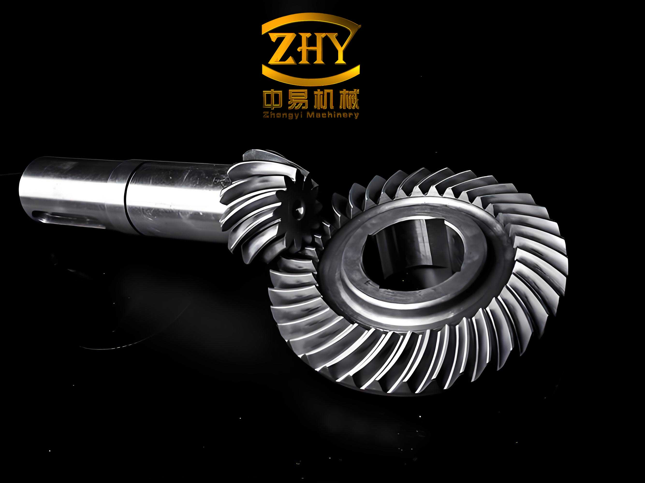
The physical mapping of a spiral bevel gear pair must always be conducted on both gears together. They are manufactured and installed as pairs, and replacing only one usually leads to poor meshing and rapid failure. The single most critical measurement is the mounting distance (A1 and A2). Inaccuracy here can prevent proper installation or lead to incorrect tooth contact, causing noise, wear, or breakage. Other dimensional parameters are measured as reference values and later refined through calculation to conform to standards.
The mapping process involves a sequence of steps. First, count the teeth (z1, z2) and determine the hand of spiral. Facing the tooth surface, if the curve from the midpoint to the toe rotates clockwise, it is a right-hand spiral; counterclockwise indicates a left-hand spiral. The shaft angle (Σ) is usually 90° in most reducers. The pitch cone angles (δ1, δ2) are calculated. For a 90° shaft angle, the formula simplifies to: $$\delta_1 = \arctan\left(\frac{z_1}{z_2}\right) = \arctan\left(\frac{1}{u}\right)$$ and $$\delta_2 = 90° – \delta_1$$. In the general case, the calculation is: $$\delta_1 = \arctan\left[\frac{\sinΣ}{u + \cosΣ}\right]$$, $$\delta_2 = Σ – \delta_1$$.
Measuring the tip diameter (da) requires care. For even-numbered teeth, it can be measured directly across. For odd-numbered teeth, measurement should be taken relative to the bore or shaft centerline, ideally using a bench center or comparator to average multiple readings. However, since SEW spiral bevel gears often lack a machined back cone and may have chamfered tips, these values are only preliminary. The approximate module can be estimated from the tip diameter: $$m’ \approx \frac{d_a}{z + 2h_a^*}$$, but this is highly tentative.
The total tooth height (h) is measured at the heel of the tooth using a depth gauge. This measurement is also a reference. The mounting distance (A) is measured indirectly when a rolling tester is unavailable. The gear pair is placed on a surface plate, and shims or blocks are used to approximate the correct shaft angle (90°). The normal backlash should be minimized (jn min < 0.5 mm). Then, dimensions L and H (or L, l as shown in diagrams) are measured to calculate A1 and A2. The formulas are: $$A_1 = L – \frac{d_{a2}}{2}$$ and $$A_2 = H – \frac{d_{a1}}{2}$$, or using auxiliary measurements. This method, while practical, requires precision.
The outer cone distance (Re‘) is measured as shown in figures, often by measuring the distance across the back faces of the gear blanks and halving it. This measured Re‘ provides another check for the module: $$m’ = \frac{2R_e’}{\sqrt{z_1^2 + z_2^2}}$$.
Determining the mean spiral angle (βm) and pressure angle (α) is crucial for identifying the tooth system. The imprint method is practical. An imprint of the top land over about 1/6 of the circumference is made on paper. Three points on the tip circle define a center O’. On a distinct tooth curve, points at the heel, midpoint, and toe are used to find the center of curvature D. The angle ∠O’MD is measured, and the mean spiral angle is: $$β_m = 90° – ∠O’MD$$. The pressure angle can be measured using gear tooth calipers or by matching imprint angles with standard templates; for SEW gears, it is typically 20°.
With these measurements, we can consolidate data. For example, from a typical mapping session on an SEW-type reducer, we might obtain:
| Measured Parameter | Symbol | Pinion | Gear | Notes |
|---|---|---|---|---|
| Number of Teeth | z | 20 | 32 | Direct count |
| Hand of Spiral | – | Right | Left | Visual inspection |
| Tip Diameter | da‘ | 187 mm | 290 mm | Approximate, ref. |
| Total Tooth Height | h’ | 17 mm | 17 mm | Measured at heel |
| Mounting Distance | A | 150 mm | 150 mm | Calculated from L, H |
| Outer Cone Distance | Re‘ | 169 mm | Measured/2 | |
| Mean Spiral Angle | βm | 35° | Imprint method | |
| Pressure Angle | α | 20° | Assessed/measured | |
From the preliminary data, multiple estimates for the module exist: from tip diameters (m1‘ ≈ 9.35, m2‘ ≈ 9.06) and from outer cone distance (m’ ≈ 8.957). Rounding to the nearest standard module suggests m = 9. Verification using the total tooth height formula for the Gleason system: $$h = (2h_a^* + c^*) \cdot m = (2 \times 0.85 + 0.188) \times 9 = 16.992 \text{ mm}$$. This closely matches the measured 17 mm, confirming the module and tooth system identification. Therefore, we proceed with m=9, Gleason system.
Now, we can calculate all other geometric parameters definitively. The calculations follow standard spiral bevel gear geometry formulas. First, the pitch diameters: $$d_1 = m \cdot z_1 = 9 \times 20 = 180 \text{ mm}$$, $$d_2 = m \cdot z_2 = 9 \times 32 = 288 \text{ mm}$$. The gear ratio: $$u = z_2 / z_1 = 32/20 = 1.6$$. The pitch cone angles for Σ=90°: $$\delta_1 = \arctan(20/32) = \arctan(0.625) = 32.0054°$$, $$\delta_2 = 90° – 32.0054° = 57.9946°$$. The exact outer cone distance: $$R_e = \frac{m}{2} \sqrt{z_1^2 + z_2^2} = \frac{9}{2} \sqrt{20^2 + 32^2} = 4.5 \times \sqrt{400 + 1024} = 4.5 \times \sqrt{1424} \approx 4.5 \times 37.736 \approx 169.812 \text{ mm}$$.
The face width (b) is often measured directly. For spiral bevel gears, a common face width factor is ψR = b / Re ≈ 0.3. If measured b=50 mm, then ψR = 50/169.812 ≈ 0.294, which is reasonable. The profile shift coefficients (x1, x2) and tangential shift coefficients (xt1, xt2) are obtained from handbook tables based on z1=20 and u=1.6. For Gleason system, typical values might be x1=0.24, x2=-0.24 and xt1=0.05, xt2=-0.05. These values optimize tooth strength and contact pattern.
The addendum and dedendum are calculated. For the Gleason system, the addendum for the pinion and gear are not equal due to profile shift. The addendum height: $$h_a = m(h_a^* + x)$$. For the pinion: $$h_{a1} = 9 \times (0.85 + 0.24) = 9 \times 1.09 = 9.81 \text{ mm}$$. For the gear: $$h_{a2} = 9 \times (0.85 – 0.24) = 9 \times 0.61 = 5.49 \text{ mm}$$. The dedendum: $$h_f = m(h_a^* + c^* – x)$$. For the pinion: $$h_{f1} = 9 \times (0.85 + 0.188 – 0.24) = 9 \times 0.798 = 7.182 \text{ mm}$$. For the gear: $$h_{f2} = 9 \times (0.85 + 0.188 + 0.24) = 9 \times 1.278 = 11.502 \text{ mm}$$. The total tooth height: $$h = h_{a1} + h_{f1} = 9.81 + 7.182 = 16.992 \text{ mm}$$ (same for gear: 5.49+11.502=16.992 mm).
The tip and root angles are determined from the dedendum and addendum angles. The root angle: $$\theta_f = \arctan(h_f / R_e)$$. For the pinion: $$\theta_{f1} = \arctan(7.182 / 169.812) \approx \arctan(0.04228) \approx 2.4218°$$. For the gear: $$\theta_{f2} = \arctan(11.502 / 169.812) \approx \arctan(0.06772) \approx 3.8749°$$. The addendum angle: $$\theta_a = \arctan(h_a / R_e)$$. For the pinion: $$\theta_{a1} = \arctan(9.81 / 169.812) \approx \arctan(0.05776) \approx 3.8749°$$. For the gear: $$\theta_{a2} = \arctan(5.49 / 169.812) \approx \arctan(0.03233) \approx 2.4218°$$. Note the complementary relationship due to the 90° shaft angle.
The apex to crown distance (Ak), also called the outer cone height, is crucial for mounting. It is the distance from the apex of the pitch cone to the crown (back face) of the gear. It can be calculated as: $$A_k = R_e \cos\delta – h_a \sin\delta$$. For the pinion: $$A_{k1} = 169.812 \times \cos(32.0054°) – 9.81 \times \sin(32.0054°) \approx 169.812 \times 0.8480 – 9.81 \times 0.5299 \approx 144.0 – 5.20 \approx 138.80 \text{ mm}$$. For the gear: $$A_{k2} = 169.812 \times \cos(57.9946°) – 5.49 \times \sin(57.9946°) \approx 169.812 \times 0.5299 – 5.49 \times 0.8480 \approx 90.0 – 4.66 \approx 85.34 \text{ mm}$$.
The mounting distance (A) is the distance from a reference datum (often the back face of the gear or a shoulder on the shaft) to the apex of the pitch cone. From the earlier indirect measurement, we had A=150 mm for both. This can be verified: the distance from the back face to the apex is Ak, so the mounting distance from a datum further back would be A = Ak + Δ, where Δ is the distance from the datum to the gear back face. In our case, if the measured A is 150 mm and Ak is 138.80 mm for the pinion, then the distance from the mounting datum to the gear back face (support end distance, H) is: $$H_1 = A_1 – A_{k1} = 150 – 138.80 = 11.20 \text{ mm}$$. For the gear: $$H_2 = A_2 – A_{k2} = 150 – 85.34 = 64.66 \text{ mm}$$. These values should match physical measurements on the housing or shaft.
The tip diameter is recalculated precisely: $$d_a = d + 2h_a \cos\delta$$. For the pinion: $$d_{a1} = 180 + 2 \times 9.81 \times \cos(32.0054°) \approx 180 + 19.62 \times 0.8480 \approx 180 + 16.64 \approx 196.64 \text{ mm}$$. For the gear: $$d_{a2} = 288 + 2 \times 5.49 \times \cos(57.9946°) \approx 288 + 10.98 \times 0.5299 \approx 288 + 5.82 \approx 293.82 \text{ mm}$$. These corrected values differ from the rough measurements due to chamfers and measurement errors, confirming the need for calculation.
A comprehensive table of all calculated parameters for this spiral bevel gear pair is thus assembled:
| Parameter | Symbol | Pinion | Gear | Formula/Note |
|---|---|---|---|---|
| Tooth System | – | Gleason | Identified from βm, α, coefficients | |
| Pressure Angle | α | 20° | ||
| Module | m | 9 | Standardized from measurements | |
| Number of Teeth | z | 20 | 32 | |
| Shaft Angle | Σ | 90° | Assumed/measured | |
| Gear Ratio | u | 1.6 | z2/z1 | |
| Mean Spiral Angle | βm | 35° | Measured via imprint | |
| Pitch Cone Angle | δ | 32.0054° | 57.9946° | δ1=arctan(z1/z2), δ2=90°-δ1 |
| Pitch Diameter | d | 180 mm | 288 mm | d = m·z |
| Outer Cone Distance | Re | 169.812 mm | Re = (m/2)√(z1²+z2²) | |
| Face Width | b | 50 mm | Measured | |
| Face Width Factor | ψR | 0.294 | b / Re | |
| Profile Shift Coefficient | x | 0.24 | -0.24 | From handbook (Gleason) |
| Tangential Shift Coefficient | xt | 0.05 | -0.05 | From handbook (Gleason) |
| Addendum Coefficient | ha* | 0.85 | Gleason system | |
| Clearance Coefficient | c* | 0.188 | Gleason system | |
| Addendum | ha | 9.81 mm | 5.49 mm | ha = m(ha* + x) |
| Dedendum | hf | 7.182 mm | 11.502 mm | hf = m(ha* + c* – x) |
| Total Tooth Height | h | 16.992 mm | h = ha + hf | |
| Root Angle | θf | 2.4218° | 3.8749° | θf = arctan(hf/Re) |
| Addendum Angle | θa | 3.8749° | 2.4218° | θa = arctan(ha/Re) |
| Tip Cone Angle | δa | 35.8803° | 60.4164° | δa = δ + θa |
| Root Cone Angle | δf | 29.5836° | 54.1197° | δf = δ – θf |
| Tip Diameter | da | 196.64 mm | 293.82 mm | da = d + 2hacosδ |
| Apex to Crown Distance | Ak | 138.80 mm | 85.34 mm | Ak = Recosδ – hasinδ |
| Mounting Distance | A | 150 mm | 150 mm | Measured/calculated reference |
| Support End Distance | H | 11.20 mm | 64.66 mm | H = A – Ak |
In practice, after calculating these parameters, the gear design is verified through contact pattern checks on a rolling tester or via assembly trials. The successful application of such mapped and calculated spiral bevel gears in field repairs, for instance in mining equipment, demonstrates the viability of this method. Properly mapped gears exhibit smooth operation, minimal noise, and expected service life.
Beyond the basic geometry, several advanced considerations are essential for accurate spiral bevel gear mapping. The calculation of equivalent spur gear teeth numbers for strength checks is important. The formative number of teeth: $$z_v = \frac{z}{\cosδ}$$. For the pinion: $$z_{v1} = \frac{20}{\cos(32.0054°)} \approx \frac{20}{0.8480} \approx 23.58$$. For the gear: $$z_{v2} = \frac{32}{\cos(57.9946°)} \approx \frac{32}{0.5299} \approx 60.39$$. These values are used in bending stress calculations according to ISO or AGMA standards.
The normal module is also a derived parameter: $$m_n = m \cosβ_m$$. With βm=35°, $$m_n = 9 \times \cos(35°) \approx 9 \times 0.8192 \approx 7.373 \text{ mm}$$. The normal pressure angle: $$α_n = \arctan(\tanα \cosβ_m) = \arctan(\tan20° \times \cos35°) \approx \arctan(0.3640 \times 0.8192) \approx \arctan(0.2982) \approx 16.61°$$.
Backlash is a critical assembly parameter. The theoretical circumferential backlash at the large end can be estimated from the measured center distance variation or directly specified. The normal backlash jn is related to the circumferential backlash jt by: $$j_n = j_t \cosα \cosβ_m$$. For proper operation, backlash must be within tolerances, typically 0.05-0.15 mm for medium-sized gears.
When mapping severely worn or damaged spiral bevel gears, additional techniques are required. The pitch cone apex location can be inferred from unworn sections or symmetry. Measurement of several teeth around the circumference and averaging is crucial to mitigate local wear errors. In cases where the original tooth system is uncertain, comparing calculated parameters with standard systems (Gleason vs. Enimus) by testing both in calculations and checking against physical features like tooth depth and curvature can resolve the identity.
Modern tools can aid traditional mapping. 3D scanning technology allows for capturing the entire tooth surface geometry, enabling reverse engineering through point cloud data and CAD software. However, the fundamental principles of gear geometry and parameter derivation remain unchanged. The mapping process still relies on correctly identifying key parameters like module, pressure angle, and spiral angle from the physical gear.
In conclusion, the mapping and calculation of spiral bevel gears, particularly from SEW series reducers, is a meticulous but manageable process when approached systematically. The core steps involve: accurate measurement of mounting distances; careful counting of teeth and determination of spiral hand; estimation of module from multiple reference measurements; identification of the tooth system via spiral angle and pressure angle; and finally, comprehensive calculation of all geometric parameters using standard formulas, rounding to accepted standards. The use of tables and formulas, as demonstrated extensively here, is indispensable for organizing data and ensuring consistency. Mastery of this process empowers maintenance engineers to effectively repair and replace critical spiral bevel gear drives, minimizing downtime and ensuring reliable operation in demanding industrial applications. The spiral bevel gear, with its complex geometry, demands respect, but through diligent mapping and calculation, its secrets can be unlocked for successful replication and application.