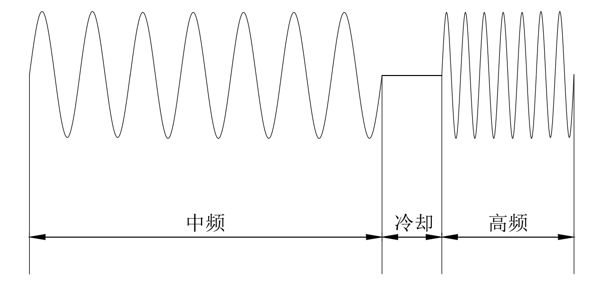
The switching time of medium and high frequency current is involved in the time-sharing of dual frequency induction heating of bevel gear by segmented dual frequency induction heating. Segmented dual frequency induction heating can be realized by alternately applying medium and high frequency currents in one induction coil, or two induction coils can be used, that is, medium and high frequency currents can be applied to the two induction coils respectively. Either way, there is a problem of switching time in the process of medium and high frequency switching. However, the switching time will be much shorter when medium and high frequency currents are alternately connected in the same coil. In the process of medium and high frequency switching, there is no heat source on the bevel gear, which is equivalent to the process of air cooling. Next, the influence of medium and high frequency switching time on dual frequency induction heating of bevel gear is analyzed, including the sequence of medium and high frequency current of cooling time, as shown in Figure 1. The electrical parameters of double frequency induction heating of bevel gear are as follows: the high frequency current density is 6.0 × 10⁷a / m2, high frequency current frequency of 100kHz, medium frequency current density of 1.6 × 10⁸a / m2, the frequency of medium frequency current is 6KHz respectively. First conduct medium frequency induction heating for 40s, then cool for 4S, 9s and 14s respectively, and then conduct high frequency induction heating for 15s.
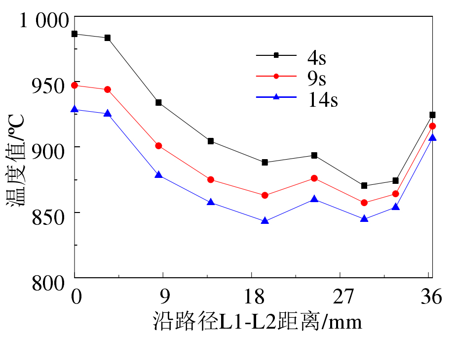
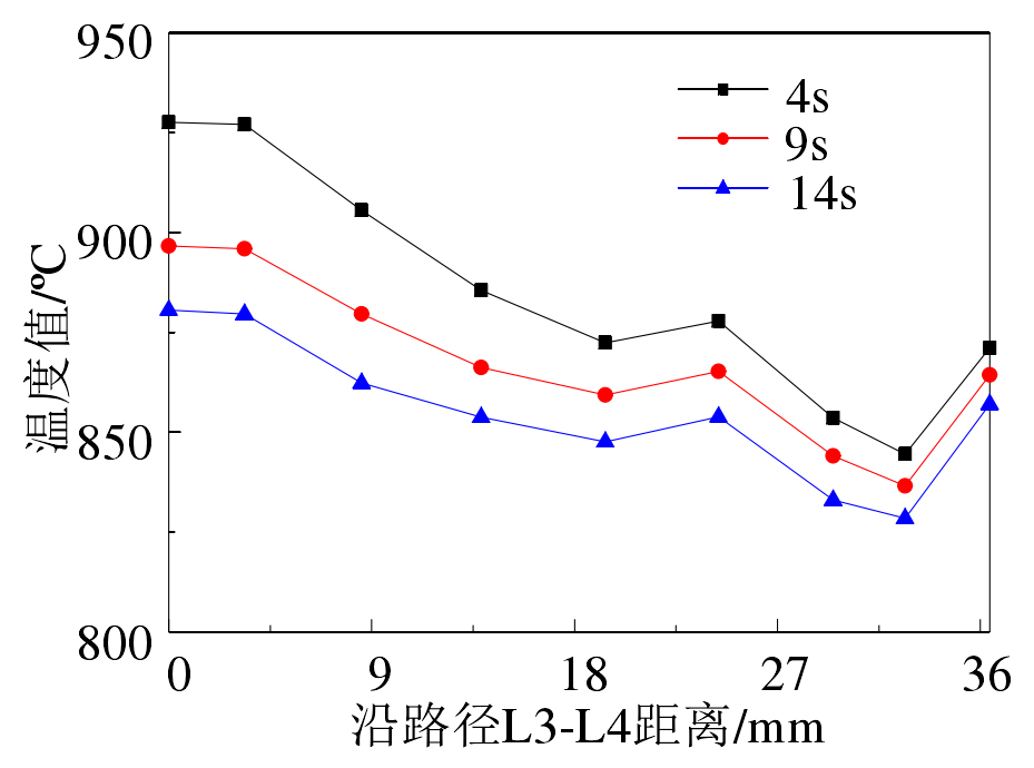
Paths L1-L2 and L3-L4 are curves in the direction of bevel gear tooth profile. The tooth profile path includes three parts: tooth top, tooth surface and tooth root. The structures of these three parts on the gear are very different, resulting in different dominant cooling modes of the three parts in the cooling process. For the crown and tooth surface of bevel gear, the contact area with air is large, and there are relatively more convective and radiant heat dissipation. For the tooth root, the convective heat dissipation and radiation heat dissipation are small, but the tooth root is closest to the gear matrix. During induction heating, the matrix temperature changes little, so the heat conduction heat dissipation is large.
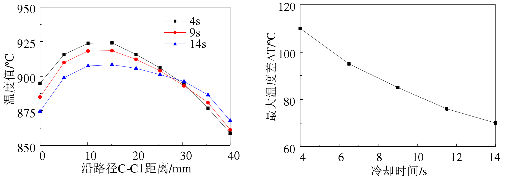
Before the cooling process, the gear temperature is heated to 900 º C through medium frequency induction heating, and then high frequency induction heating is carried out. The temperature curves of paths L1-L2 and L3-L4 are shown in Figure 2.
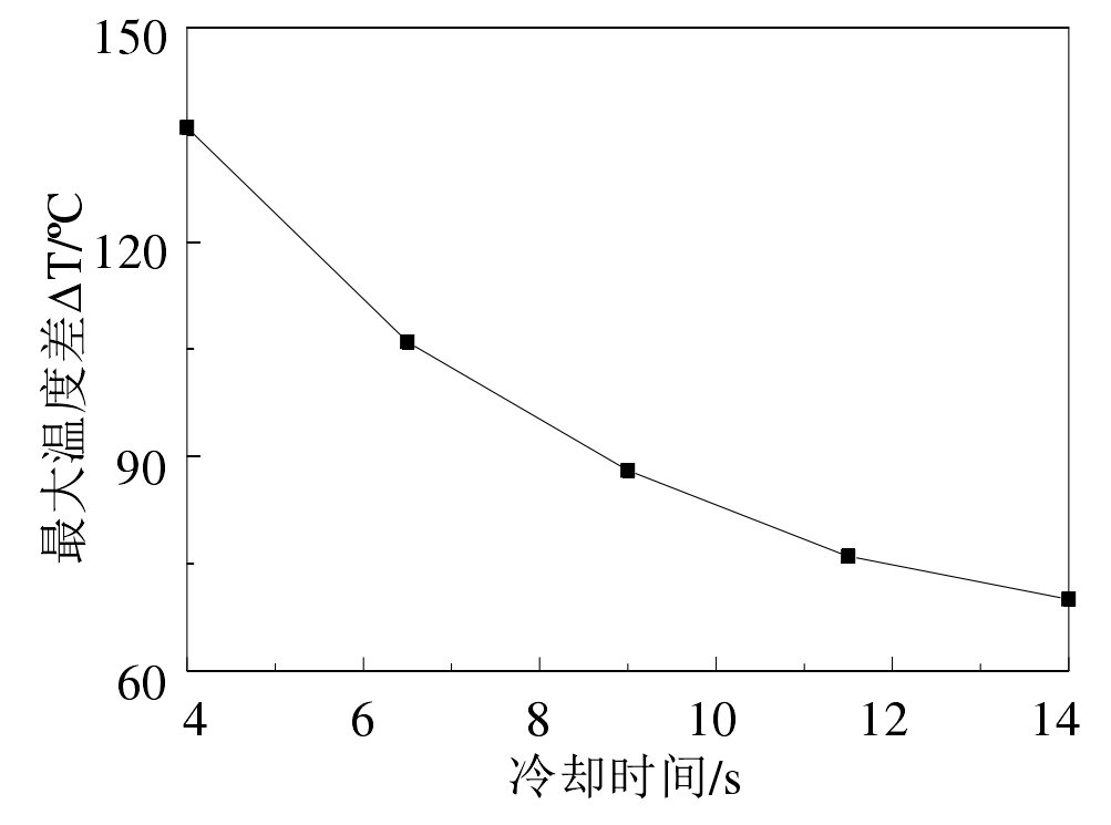
As can be seen from Figure 2, the longer the cooling time, the smaller the profile temperature value. It can be seen from Fig. 2a) and b) that the temperature values at the crown and tooth surface of the bevel gear change greatly and the temperature values at the tooth root change slightly at different cooling times. As can be seen from figure 2C), with the increase of cooling time, the maximum value of temperature difference on tooth profile path L1-L2 becomes smaller and smaller, indicating that the temperature field on tooth profile becomes more and more uniform. However, too long cooling time will not only reduce the surface temperature of bevel gear and fail to reach the austenite temperature, but also too long cooling time, that is, too long induction heating time, will lead to coarse surface grain, which is not conducive to the surface hardening quality of bevel gear.
The small end of the bevel gear has a compact structure and is close to the induction coil. Therefore, in the process of induction heating, the induction heating efficiency of the small end of the bevel gear is high. For the cooling process in the process of medium and high frequency switching, the cooling rates of the small end and the large end are also affected by the structure of the bevel gear. The cooling rate of the large and small ends is also related to the maximum temperature position in the direction of the tooth end. During the cooling process, the temperature will be transmitted from the high-temperature area to the low-temperature area. If the position of the highest temperature area along the tooth width direction is close to the large end, the temperature at the large end will decrease a little slower. Similarly, three paths are selected to analyze the uniformity of the temperature field in the tooth width direction of the bevel gear, as shown in Figure 3.
As can be seen from Fig. 3, along the tooth width direction of the bevel gear, the temperature distribution at the top, root and middle of the tooth surface is obviously different, and the highest temperature areas of the three positions are located at different positions in the tooth width direction respectively. As can be seen from Fig. 3a), the position with the highest temperature on the addendum path a-a1 is located at the small end, which is mainly related to the compact structure of the small end of the bevel gear. Both the big end and the small end have “end effect”, which leads to high induction heating efficiency at both ends of the bevel gear. From Fig. 3b), it is obvious that the temperature at both ends is higher than that at the middle part, but it is not obvious from the large end in Fig. 3a), which is mainly due to the large distance between the large end and the induction coil, and the “end effect” is not strong, while the small end is close to the induction coil, and the “end effect” is obvious. From Fig. 3a), it can be seen that the temperature at the small end is significantly higher than that at other positions. Comparing the three curves in Fig. 3a), it can be seen that the cooling time also increases by 5S, and the rate of temperature drop on the tooth top path a-a1 decreases. It can also be seen from Fig. 3b) and Fig. 3C) that the distance between the curve of cooling for 4S and the curve of cooling for 9s is large, and the distance between the curve of cooling for 9s and the curve of cooling for 14s is small.
It can be seen from Figure 3B) that the temperature at both ends of the bevel gear is high, which is mainly caused by the “end effect”. In actual production, the magnetic field distribution can be changed by placing conductive magnets at both ends of the gear, so as to reduce the “end effect”. It can also be seen from Figure 3B) that the location of the lowest temperature area on path b-b1 is close to the big end, and the temperature of the big end is slightly lower than that of the small end, which is related to the low induction heating efficiency of the big end, and the volume of the big end is larger than that of the small end, resulting in strong heat conduction effect. In addition, during the cooling process, the heat lost by the big end is also more. As can be seen from Fig. 3C), the position with the highest temperature on path c-c1 at the tooth root is located in the middle of the tooth width and close to the big end. The temperature distribution on path c-c1 is almost opposite to that on path b-b1, which is determined by the distribution characteristics of magnetic field and magnetic induction intensity during induction heating. The induction linear density in the middle of tooth width is large.
As can be seen from Fig. 3D), the maximum temperature difference in the tooth width direction decreases with the increase of cooling time, that is, increasing the cooling time is conducive to reducing the temperature difference in the tooth width direction. However, too long cooling time will lead to excessive reduction of gear surface temperature and great changes in permeability and other parameters, which will lead to the loss of preheating effect of medium frequency induction heating.

