
Due to the existence of helical angles, the meshing stiffness of helical gears not only varies with the variation of rotational angular displacement, but also varies at different positions on the same meshing line at the same time. By using the slicing method and the integration idea, the helical gear can be divided into a series of sufficiently small equal thickness slices along the axis, each slice being equivalent to a spur gear, as shown in Figure 1. By calculating the meshing stiffness of each straight gear slice and integrating it, the time-varying meshing stiffness of a single tooth of a helical gear can be obtained.
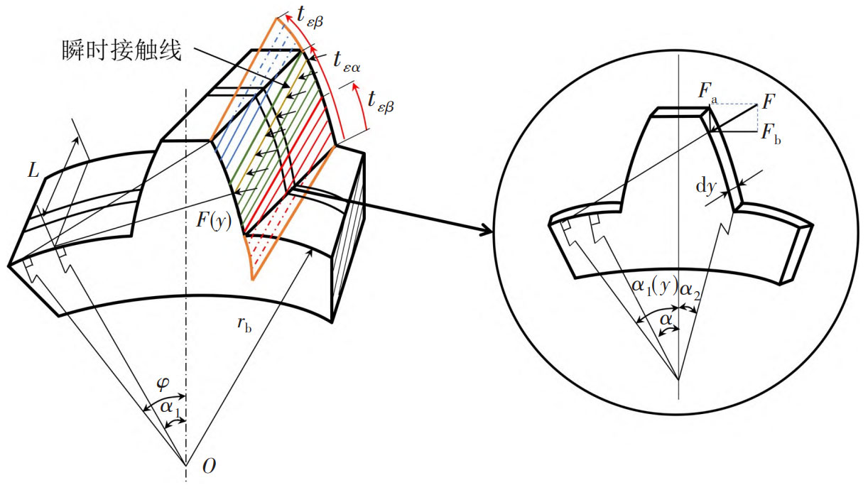
The time-varying meshing stiffness of spur gears consists of five parts: bending stiffness (kb), shear stiffness (ks), axial compression stiffness (ka), matrix stiffness (k) f, and Hertz contact stiffness (kh). The expression for the stiffness of each part is:
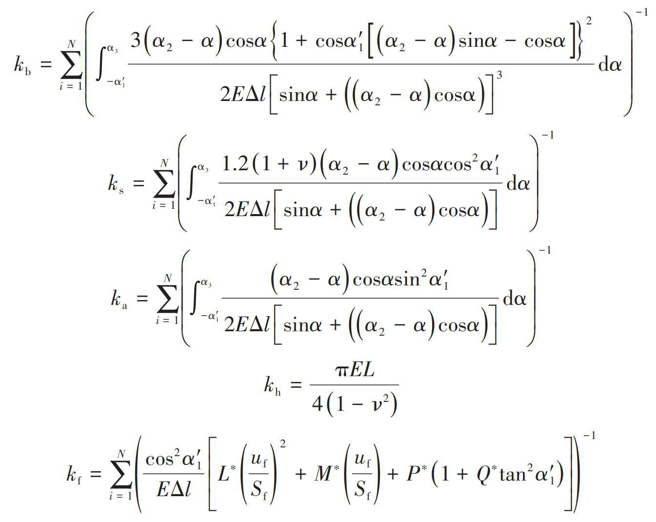
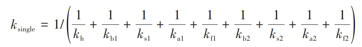
In the formula, N is the number of slices along the tooth width direction. By processing each stiffness component in parallel, the single tooth meshing stiffness that meshes with each other can be obtained as:
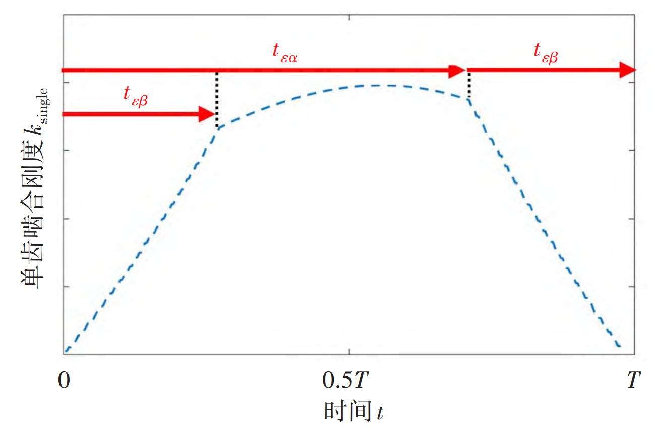
The meshing stiffness variation process of a single gear tooth during the complete cycle T from entering meshing to exiting meshing is shown in Figure 2.
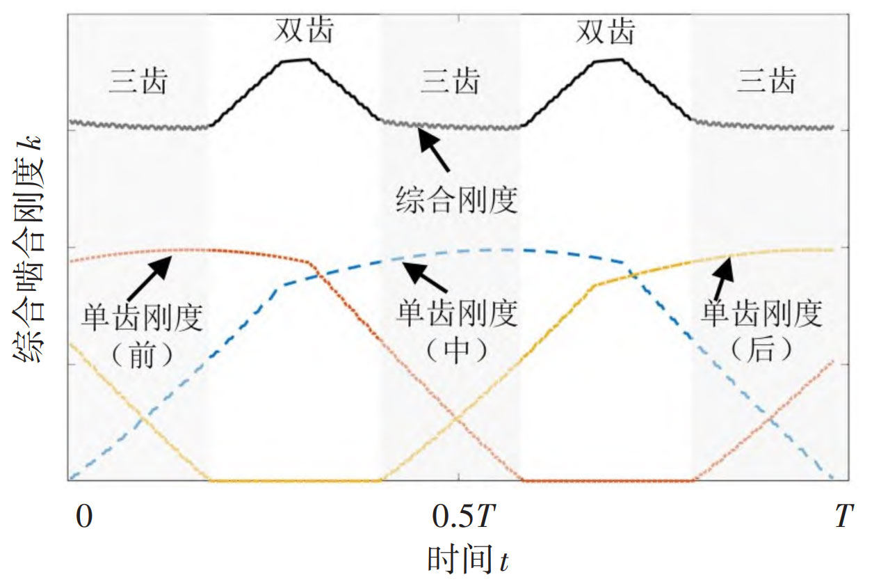
For helical gear systems with a total overlap between 2 and 3, there may be alternating contact between two and three teeth during the meshing process. The comprehensive meshing stiffness of a gear system is the effect of the combined action of various tooth pairs engaged simultaneously, and its variation process is shown in Figure 3.
Convert the comprehensive time-varying meshing stiffness k (t) approximately into the form of third harmonic:
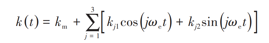
In the formula, km is the average meshing stiffness, and kj1 and kj2 are the harmonic coefficients, ω E is the meshing frequency.