
In this paper, I explore the dynamic characteristics of the 2K-V type cycloidal drive, a precision reduction mechanism widely employed in industrial robotics and automation systems. The demand for high positioning accuracy and low vibration in such cycloidal drives has intensified, necessitating a deeper understanding of their vibrational behavior. While prior research has extensively addressed accuracy aspects, dynamic performance studies remain limited. My work builds upon existing kinetic models to investigate how key design parameters influence the meshing stiffness and natural frequencies of the cycloidal drive system, all while maintaining the external dimensions and basic structure of the reducer. The core focus is on the cycloidal drive component, which is critical for the overall performance of the 2K-V reducer.
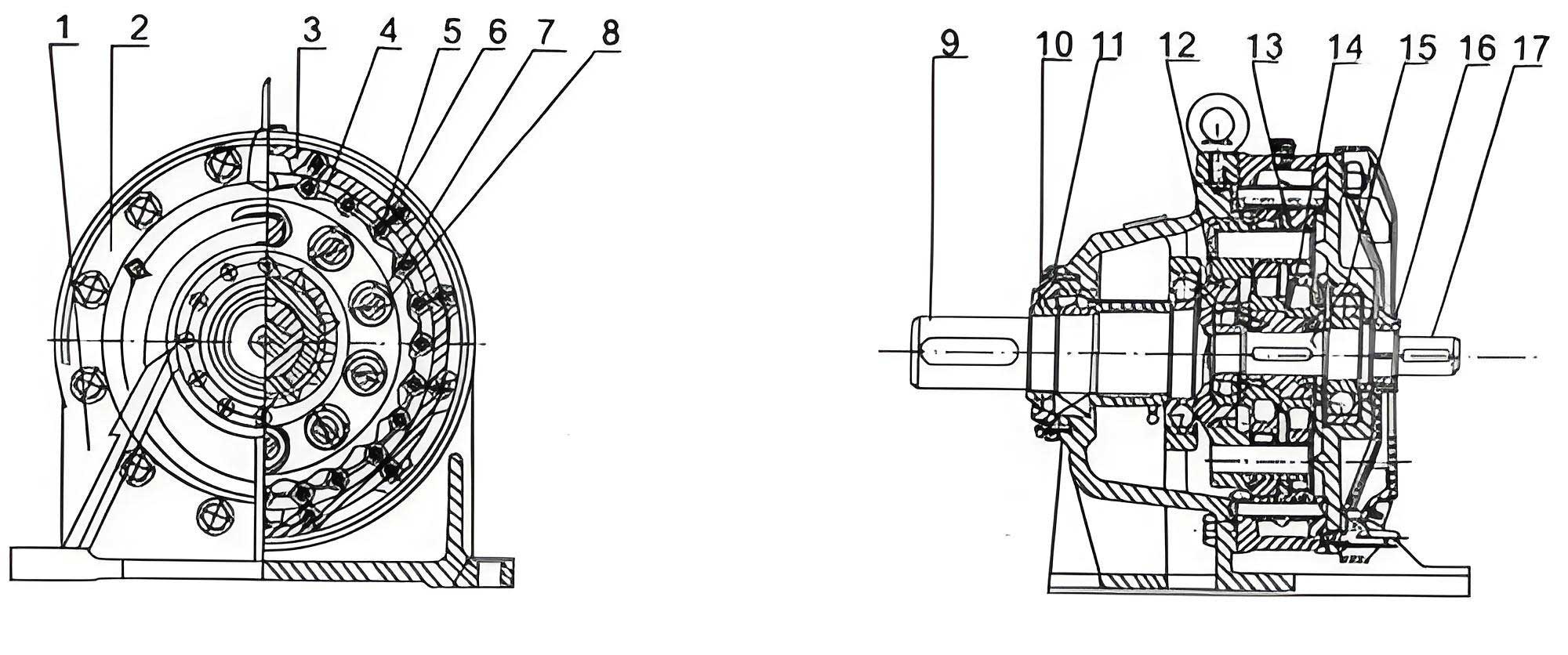
The 2K-V reducer incorporates a two-stage reduction system. The first stage involves a high-speed reduction via an input sun gear and two symmetrically arranged planetary gears. The rotational motion is then transferred to two crankshafts, driving two cycloidal discs to perform eccentric motion. With the pin gear housing fixed, the reverse rotation of the cycloidal discs is output through the planet carrier, achieving the second-stage reduction. This configuration gives the cycloidal drive its compactness and high reduction ratio. Understanding the dynamics of this cycloidal drive is essential for optimizing its performance.
To analyze the system, I established a detailed dynamic model. The model considers multiple degrees of freedom (DOFs) to capture the essential motions. It includes rotational DOFs for the input shaft, sun gear, planetary gears, cycloidal discs, crankshafts, and the planet carrier, as well as planar motion DOFs for the centers of the planetary gears and cycloidal discs. Using the lumped mass method, the equations of motion are derived. All displacements are unified into linear displacements for consistency. The general form of the equation of motion is:
$$ m\ddot{x} + c\dot{x} + kx = 0 $$
Here, \( m \) represents the equivalent mass matrix of the system, \( c \) is the damping matrix, \( k \) is the equivalent stiffness matrix, and \( x \), \( \dot{x} \), and \( \ddot{x} \) are the displacement, velocity, and acceleration vectors, respectively. The stiffness matrix \( k \) incorporates various stiffness components from the cycloidal drive and other elements, such as the meshing stiffness of the cycloidal disc and pin gears (\( k_{ci} \)), the bending stiffness of the crankshaft at the cycloidal disc installation points (\( k_{ciHi} \)), the torsional stiffness of the input shaft (\( k_I \)), and the meshing stiffness of the involute gears (\( k_{spi} \)). The model’s complexity allows for a comprehensive analysis of how each parameter affects the overall dynamic response, particularly the natural frequencies that dictate vibration performance.
My investigation centers on a specific 2K-V6 cycloidal drive with the following parameters: sun gear teeth \( z_s = 10 \), planetary gear teeth \( z_p = 34 \), module \( m = 1 \, \text{mm} \), pressure angle \( \alpha = 20^\circ \), cycloidal disc teeth \( z_c = 29 \), pin gear teeth \( z_b = 30 \), short-width coefficient \( K_1 = 0.675 \), eccentricity \( a = 0.9 \, \text{mm} \), pin radius \( r = 2 \, \text{mm} \), pin distribution circle radius \( R = 40 \, \text{mm} \), total reduction ratio \( i = 103 \), output speed \( 30 \, \text{r/min} \), and rated load torque \( T = 58 \, \text{N·m} \). By varying key parameters within practical ranges, I assessed their impact on the meshing stiffness of the cycloidal drive and the fundamental natural frequency of the entire system.
The first parameter I examined is the tooth profile modification of the cycloidal disc. Modification is often applied to ensure proper lubrication and reduce friction by introducing a slight clearance. The modification is characterized by a coefficient \( \lambda \). I analyzed the relationship between \( \lambda \) and the meshing stiffness \( k_c \) of the cycloidal drive. As \( \lambda \) increases, the initial backlash between the cycloidal disc and the pins grows. Under a constant load torque, this increased backlash leads to larger normal displacements, reducing the number of teeth in contact and consequently lowering the overall meshing stiffness. Furthermore, larger elastic deformations and the thin-walled structure of the cycloidal disc exacerbate the stress concentration, further degrading stiffness. The results for different \( \lambda \) values are summarized below:
| Modification Coefficient \( \lambda \) | Relative Meshing Stiffness Change | Qualitative Effect on Cycloidal Drive Dynamics |
|---|---|---|
| 0 | Baseline (100%) | Maximum stiffness, but potential lubrication issues. |
| 2 | Noticeable decrease | Improved lubrication, reduced stiffness. |
| 4 | Significant decrease | Further reduction in stiffness and load-sharing ability. |
| 6 | Pronounced decrease | Lowest stiffness, high contact stress, critical for thin-walled disc. |
The mathematical relationship can be expressed through the contact deformation analysis. The normal load per tooth \( F_n \) relates to the total torque \( T \) and the effective number of teeth \( N_{eff} \), which decreases with \( \lambda \). The mesh stiffness \( k_c \) is approximately proportional to \( N_{eff} \):
$$ k_c \propto N_{eff} = f(z_c, \lambda, \delta) $$
where \( \delta \) is the deformation. For a constant \( T \), as \( \lambda \) increases, \( N_{eff} \) decreases, so \( k_c \) drops. This highlights a trade-off in cycloidal drive design: some modification is necessary for practical operation, but excessive modification severely compromises stiffness and dynamic performance.
Next, I analyzed the influence of the short-width coefficient \( K_1 \), a fundamental parameter defining the trochoidal profile of the cycloidal drive. It affects the curvature of the cycloidal tooth and the eccentricity. The curvature radius \( \rho_0 \) at any point on the cycloidal profile is given by:
$$ \rho_0 = \frac{R(1 + K_1^2 – 2K_1 \cos\phi)^{3/2}}{K_1(z_b + 1)\cos\phi – (1 + z_b K_1^2)} $$
where \( \phi \) is the angle parameter. I investigated two ranges for \( K_1 \). For larger values (0.68 to 0.90), as \( K_1 \) increases, the convex portion of the tooth profile becomes more pronounced, and the minimum curvature radius decreases. This necessitates smaller pin radii to avoid interference. Simultaneously, the eccentricity \( a = K_1 R / z_b \) increases, making the cycloidal disc’s thin-walled section even thinner. The combined effect is higher contact stress and reduced meshing stiffness. This trend is consistent for different cycloidal disc tooth counts (\( z_c = 19, 29, 35 \)), though the absolute stiffness values differ. The results are consolidated in the following table:
| Short-width Coefficient \( K_1 \) | Cycloidal Disc Teeth \( z_c \) | Trend in Meshing Stiffness \( k_c \) | Primary Reason |
|---|---|---|---|
| 0.68 – 0.90 (Increasing) | 19, 29, 35 | Decreases monotonically | Increased eccentricity, thinner disc wall, higher stress. |
| 0.55 – 0.40 (Decreasing) | 29 | Decreases | Reduced pitch circle radii, shorter force arm, higher tooth load. |
For smaller \( K_1 \) values (0.55 down to 0.40), both the pitch radius of the cycloidal disc \( r_c’ = K_1 R z_c / z_b \) and the pin gear \( r_b’ = K_1 R \) decrease. This reduces the lever arm for torque transmission, meaning individual tooth loads must increase to transmit the same torque, leading to higher stress and lower effective stiffness. Therefore, an optimal range for \( K_1 \) exists. My analysis indicates that for the cycloidal drive, a \( K_1 \) between 0.6 and 0.7 offers a better balance, providing relatively higher meshing stiffness, which is beneficial for the dynamic performance of the overall reducer.
The stiffness of various components within the 2K-V reducer significantly impacts its natural frequencies. I systematically varied each stiffness component by a multiplier \( c_{ki} \) (from 1 to 6) and solved for the system’s fundamental natural frequency (base frequency). The stiffness components considered include: cycloidal disc meshing stiffness \( k_{ci} \), crankshaft bending stiffness at the cycloidal disc location \( k_{ciHi} \), crankshaft bending stiffness at the planetary gear location \( k_{pi} \), crankshaft torsional stiffness \( k_{piHi} \), input shaft torsional stiffness \( k_I \), and involute gear meshing stiffness \( k_{spi} \). The results are graphically interpreted and summarized in the table below. The fundamental frequency \( f_0 \) is most sensitive to changes in \( k_{ci} \) and \( k_{ciHi} \).
| Stiffness Component | Multiplier \( c_{ki} \) Range | Effect on Fundamental Frequency \( f_0 \) | Recommendation for Cycloidal Drive Design |
|---|---|---|---|
| Cycloidal disc meshing stiffness \( k_{ci} \) | 1 to 6 | Sharp increase initially (up to ~30% for \( c_{ki}=3 \)), then plateaus. | Aim to increase \( k_{ci} \) by 2-3 times for optimal frequency boost. |
| Crankshaft bending stiffness \( k_{ciHi} \) | 1 to 5.5 | Noticeable increase up to \( c_{ki} \approx 2 \), then minimal change. | Increase bending stiffness moderately; beyond double offers diminishing returns. |
| Involute gear meshing \( k_{spi} \) | 1 to 6 | Negligible effect | Low priority for vibration performance improvement. |
| Input shaft torsional \( k_I \) | 1 to 6 | Very minor effect | Can be considered secondary in dynamic tuning. |
| Other stiffnesses | 1 to 6 | Insignificant effect | Focus resources on \( k_{ci} \) and \( k_{ciHi} \). |
The relationship can be approximated by considering the system as a simplified spring-mass system. The square of the natural frequency is proportional to the ratio of effective stiffness to mass: \( f_0^2 \propto k_{eff} / m_{eff} \). For the cycloidal drive, \( k_{ci} \) is a major contributor to \( k_{eff} \). The sensitivity analysis confirms that enhancing the meshing stiffness of the cycloidal disc and the crankshaft’s bending rigidity are the most effective strategies for raising the natural frequency and thus improving the vibration characteristics of the cycloidal drive system.
Another critical parameter is the pin-diameter coefficient \( K_2 \), defined as \( K_2 = R / (r \sin(\pi / z_b)) \). It relates the pin gear geometry. I analyzed its effect by varying \( K_2 \) from 1.2 to 2.0 while keeping \( R \), \( r \), and the total ratio constant. As \( K_2 \) increases, the number of pins \( z_b \) decreases (since \( R \) and \( r \) are fixed, a higher \( K_2 \) implies a smaller \( z_b \) from the formula). This reduction in \( z_b \) increases the first-stage reduction ratio slightly, but more importantly, it affects the excitation frequency. The primary excitation frequency \( f_1 \) for the cycloidal drive is determined by the second-stage output speed \( n_2 \) and the pin gear teeth count:
$$ f_1 = \frac{n_2 (z_b – 1)}{60} $$
As \( K_2 \) increases, \( z_b \) decreases, which lowers both the system’s natural frequency (due to changes in mass/stiffness distribution) and the excitation frequency \( f_1 \). The concurrent drop in excitation frequency means the risk of resonance does not necessarily increase. The data is presented below:
| Pin-diameter Coefficient \( K_2 \) | Implied Pin Gear Teeth \( z_b \) (Approx.) | Effect on System Natural Frequency | Effect on Excitation Frequency \( f_1 \) | Overall Vibration Risk |
|---|---|---|---|---|
| 1.2 | Higher | Higher natural frequency | Higher | Potentially higher if \( f_1 \) approaches natural freq. |
| 1.6 | Medium | Medium | Medium | Moderate |
| 2.0 | Lower | Lower natural frequency | Lower | Not necessarily worse; both frequencies shift down. |
Therefore, selecting a larger \( K_2 \) (around 2.0) is acceptable from a dynamic perspective for the cycloidal drive, as it maintains a safe margin between excitation and natural frequencies, despite the absolute natural frequency being lower. This parameter interacts with the cycloidal disc design and should be considered alongside \( K_1 \).
To synthesize the findings, I performed a comprehensive parametric study using the dynamic model. The equations were solved numerically for various parameter sets. The equivalent stiffness matrix \( k \) was assembled considering all couplings. For instance, the meshing stiffness of the cycloidal drive \( k_{ci} \) is not constant but varies with the engagement position. An average value over a mesh cycle was used for linear analysis, but the variation pattern was studied. The system’s eigenvalues \( \omega_n \) (natural frequencies) satisfy:
$$ \det(k – \omega_n^2 m) = 0 $$
By perturbing parameters, I tracked changes in the fundamental eigenvalue \( \omega_1 = 2\pi f_0 \). The sensitivity \( S \) of \( f_0 \) to a parameter \( p \) (like \( K_1 \) or \( \lambda \)) can be defined as:
$$ S_{f_0}^p = \frac{\partial f_0}{\partial p} \cdot \frac{p}{f_0} $$
Calculations showed high sensitivity for \( p = k_{ci} \) and \( p = K_1 \) in its mid-range. These results underscore the dominance of the cycloidal drive’s internal design on the whole reducer’s dynamics.
Furthermore, I considered the effect of load torque on the dynamic response. While the rated load was used for most analysis, varying torque influences the mesh stiffness due to nonlinear contact deformation. For the cycloidal drive, the relationship between load \( T \) and deflection \( \delta \) can be approximated by a power law, affecting the effective stiffness. This nonlinearity is more pronounced at high loads and should be considered in detailed simulations, though for the fundamental frequency analysis, a linearized model around the operating point suffices.
Damping, represented by matrix \( c \), also plays a role in vibration amplitude but has less impact on natural frequencies. In cycloidal drives, damping arises from material hysteresis, lubricant film, and joint friction. A typical damping ratio \( \zeta \) of 0.03 to 0.07 is assumed for steel components with oil lubrication. The model’s damping matrix was constructed proportional to the mass and stiffness matrices (Rayleigh damping): \( c = \alpha m + \beta k \), where \( \alpha \) and \( \beta \) are coefficients determined from modal damping ratios. This allows for transient response analysis, but the focus here remains on frequency-domain characteristics.
In addition to the parameters already discussed, the geometry of the cycloidal disc itself, such as the tooth depth and root thickness, directly affects its bending stiffness and thus the meshing stiffness. I conducted a brief analysis by varying the disc’s web thickness parameterically. A thicker web increases the bending rigidity of the cycloidal disc, contributing to higher overall \( k_{ci} \). However, this must be balanced against weight and inertia. The trade-off can be expressed through a simple beam model for the cycloidal disc tooth:
$$ k_{bend} \approx \frac{E w t^3}{4 L^3} $$
where \( E \) is Young’s modulus, \( w \) is tooth width, \( t \) is effective thickness, and \( L \) is cantilever length. Increasing \( t \) significantly boosts \( k_{bend} \), which is part of \( k_{ci} \). Therefore, material selection and geometric optimization of the cycloidal disc are crucial for enhancing the dynamic performance of the cycloidal drive.
Another aspect is the manufacturing tolerances and assembly errors. Misalignments in the crankshaft or pin gear housing can induce unequal load distribution among the cycloidal discs, effectively reducing the system’s overall stiffness. While not explicitly modeled here, such errors would manifest as reductions in the effective \( k_{ci} \) and \( k_{ciHi} \), emphasizing the need for precision in producing cycloidal drive components.
The dynamic model also allows for the analysis of mode shapes. The first few modes typically involve torsional oscillation of the output stage coupled with lateral motion of the cycloidal discs. By examining the eigenvectors, I confirmed that modes associated with the cycloidal drive deformation have the lowest natural frequencies, justifying the focus on parameters affecting this subsystem. For instance, a mode where the two cycloidal discs rock in opposition phase is highly sensitive to \( k_{ciHi} \).
To provide a holistic view, I consolidated the optimal parameter ranges based on dynamic performance for the cycloidal drive within the 2K-V reducer:
| Parameter | Symbol | Recommended Range for High Natural Frequency | Rationale |
|---|---|---|---|
| Tooth Profile Modification | \( \lambda \) | Minimal necessary for lubrication (low value) | Maximizes meshing stiffness of cycloidal drive. |
| Short-width Coefficient | \( K_1 \) | 0.60 – 0.70 | Balances curvature, eccentricity, and disc thickness for good stiffness. |
| Cycloidal Disc Meshing Stiffness | \( k_{ci} \) | As high as possible (aim 2-3x baseline) | Most sensitive parameter for raising fundamental frequency. |
| Crankshaft Bending Stiffness | \( k_{ciHi} \) | Moderately high (1.5-2x baseline) | Significant impact up to a point; over-design not beneficial. |
| Pin-diameter Coefficient | \( K_2 \) | ~2.0 | Lowers excitation frequency in tandem with natural frequency, maintaining margin. |
| Cycloidal Disc Thickness | \( t \) | Maximize within space/weight constraints | Increases bending stiffness, part of \( k_{ci} \). |
In conclusion, my dynamic analysis of the 2K-V reducer highlights the pivotal role of the cycloidal drive in determining the system’s vibrational characteristics. The meshing stiffness of the cycloidal disc and the bending stiffness of the crankshaft at the disc mounting points are the most influential factors for increasing the fundamental natural frequency. Parameters like the short-width coefficient and tooth profile modification require careful selection to balance stiffness with practical necessities like lubrication and stress. The pin-diameter coefficient affects both natural and excitation frequencies, and a value around 2.0 is advisable. This comprehensive investigation provides guidelines for designing cycloidal drives with superior dynamic performance, ensuring low vibration and high precision in applications such as robotics. Future work could involve nonlinear transient analysis and experimental validation to further refine the model and explore the effects of damping and manufacturing variances on the cycloidal drive’s real-world behavior.
Throughout this study, the term ‘cycloidal drive’ has been emphasized to underscore its centrality in the 2K-V reducer’s dynamics. The cycloidal drive is not merely a component but the heart of the reduction system, dictating its stiffness, natural frequencies, and ultimately its vibrational signature. Optimizing the cycloidal drive through the parameters discussed is essential for achieving the quiet, precise operation demanded by advanced mechanical systems.