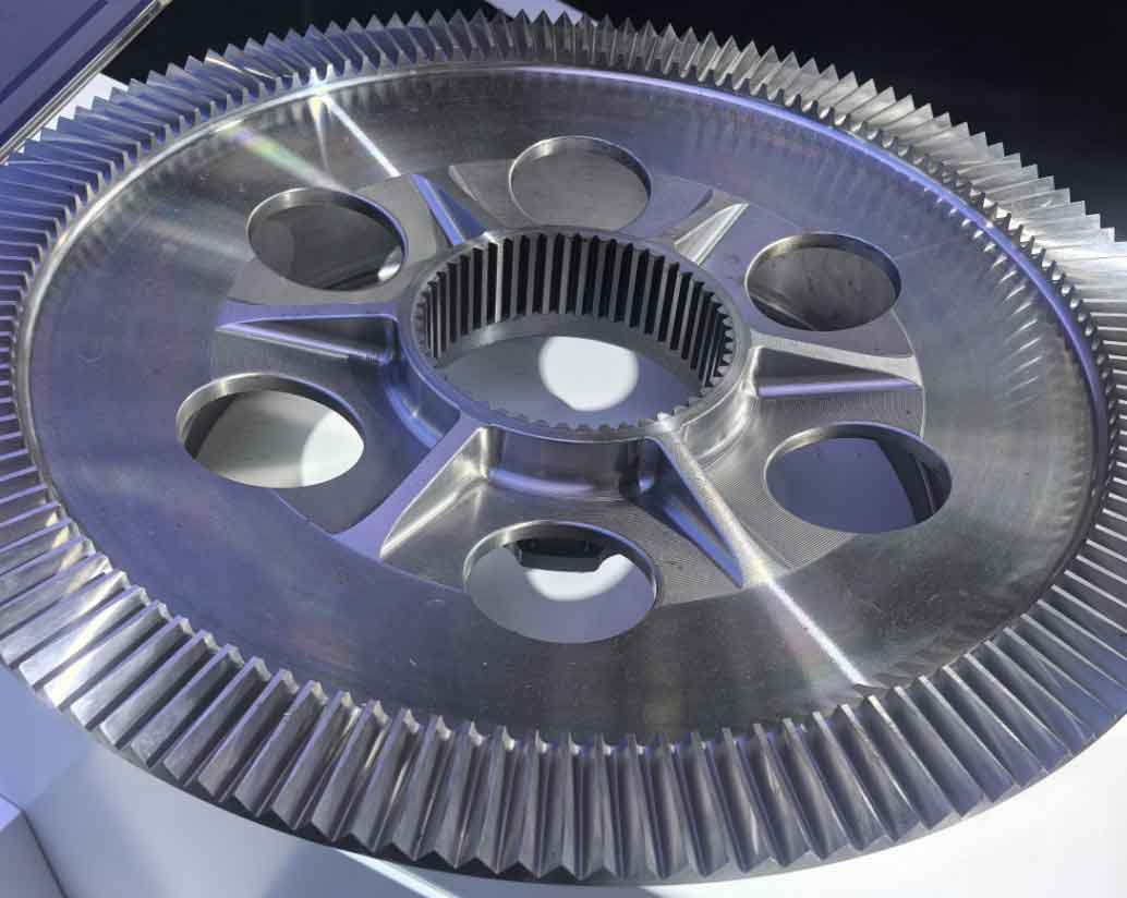
Coal shearer cutting transmission systems are characterized by compact structures and high load-bearing capacity, enabling wide-range transmission ratios. The performance of these systems directly impacts coal mining efficiency and operational safety. Transmission systems primarily comprise gear components, where inherent gear machining errors inevitably occur due to limitations in manufacturing processes, design methodologies, and human factors. These errors compromise operational stability and reliability, necessitating rigorous analysis of their dynamic effects under varying conditions.

The cutting transmission system includes motors, drums, fixed-axis gears, and pinions. Power from the motor is converted into high-torque, low-speed rotational force through multi-stage gear transmission to drive the cutting drum. Gears are critical components, and their gear machining precision determines system reliability. Common gear machining errors encompass single-pitch deviation, cumulative pitch error, and tooth profile error. Cumulative pitch error, primarily caused by backlash, significantly impacts motion accuracy. Backlash arises from gear machining tolerances and manifests as clearance between meshing teeth, introducing both benefits and drawbacks:
| Advantages | Disadvantages |
|---|---|
| Prevents jamming during engagement initiation | Induces collisions, noise, and impact forces |
| Facilitates lubrication, reducing wear | Compromises torque transmission reliability |
| Mitigates thermal expansion effects | Accelerates fatigue failure and efficiency loss |
To quantify backlash effects, we establish a dynamic model for the transmission system. The equations of motion for a gear pair with backlash are:
$$I_1\ddot{\theta}_1 + c(\dot{\theta}_1 – \dot{\theta}_2) + k f(\theta_1 – \theta_2) = T_1$$
$$I_2\ddot{\theta}_2 + c(\dot{\theta}_2 – \dot{\theta}_1) + k f(\theta_2 – \theta_1) = -T_2$$
Where \(I_1\) and \(I_2\) are moments of inertia, \(\theta_1\) and \(\theta_2\) angular displacements, \(c\) damping coefficient, \(k\) mesh stiffness, and \(T_1\), \(T_2\) applied torques. The backlash function \(f(\delta)\) is defined as:
$$
f(\delta) =
\begin{cases}
\delta – b/2 & \text{if } \delta > b/2 \\
0 & \text{if } |\delta| \leq b/2 \\
\delta + b/2 & \text{if } \delta < -b/2
\end{cases}
$$
where \(b\) denotes backlash magnitude. Minimum recommended backlash values derived from AGMA standards are:
| Normal Module (mm) | 50 mm Center Distance | 100 mm Center Distance | 200 mm Center Distance | 400 mm Center Distance | 800 mm Center Distance |
|---|---|---|---|---|---|
| 2 | 0.10 | 0.12 | 0.15 | – | – |
| 3 | 0.12 | 0.14 | 0.17 | 0.24 | – |
| 5 | – | 0.18 | 0.21 | 0.28 | – |
| 8 | – | 0.24 | 0.27 | 0.34 | 0.47 |
| 12 | – | – | 0.35 | 0.42 | 0.55 |
For MATLAB simulations, we parameterize a 1,000 kW shearer system with eight gears. Key parameters include:
| Gear | Teeth Count | Pitch Radius (mm) |
|---|---|---|
| 1 | 10 | 150 |
| 2 | 10 | 180 |
| 3 | 10 | 195 |
| 4 | 12 | 114 |
| 5 | 12 | 222 |
| 6 | 12 | 222 |
| 7 | 12 | 222 |
| 8 | 12 | 234 |
Simulations analyze angular acceleration (\(\alpha\)) under six backlash conditions (0, 0.1mm, 0.2mm, 0.3mm, 0.4mm, 0.5mm) during startup (0–20s, zero torque) and steady-state operation (20–30s, \(T = 16,989.88 + 500\pi t\) N·m). Results for Gear 2 demonstrate nonlinear dynamics:
$$ \alpha_{\text{max}} = k_1 \cdot b^2 + k_2 \cdot b + k_3 $$
where \(k_1\), \(k_2\), \(k_3\) are system-specific coefficients. At 0.5mm backlash, Gear 2’s peak angular acceleration reaches \(2.211 \times 10^4\) rad/s² versus \(4.096 \times 10^3\) rad/s² at zero backlash. Backlash amplifies torsional vibrations, particularly in early-stage gears closer to the motor:
| Gear Position | Zero Backlash | 0.1 mm Backlash | 0.5 mm Backlash |
|---|---|---|---|
| Gear 1 | 4.10 | 11.25 | 21.88 |
| Gear 2 | 4.10 | 12.83 | 22.41 |
| Gear 3 | 3.95 | 10.97 | 20.54 |
| Gear 4 | 3.82 | 12.83 | 19.76 |
| Gear 5 | 2.15 | 5.63 | 11.02 |
| Gear 6 | 1.98 | 4.21 | 9.87 |
| Gear 7 | 1.75 | 3.94 | 8.12 |
| Gear 8 | 1.60 | 3.52 | 7.33 |
Gears 1–4 exhibit 210–446% higher acceleration sensitivity than Gears 5–8 due to smaller pitch radii and larger rotational lost motion. This correlation follows:
$$ S_b = \frac{\Delta \alpha_{\text{max}}}{\Delta b} \propto \frac{1}{r_p} $$
where \(S_b\) is backlash sensitivity and \(r_p\) is pitch radius. Optimizing gear machining tolerances for early transmission stages is critical, as their kinematic errors propagate through subsequent stages. Statistical analysis of gear machining processes reveals that reducing backlash below 0.1mm in Stages 1–4 decreases angular acceleration fluctuations by 38–62% compared to 0.5mm clearance.
This analysis confirms that backlash from gear machining inaccuracies substantially degrades transmission stability. Precision control in manufacturing early-stage gears, particularly minimizing backlash below 0.1mm, is essential for enhancing shearer operational reliability. Future work will integrate wear progression models with time-varying backlash to predict long-term dynamic behavior.
