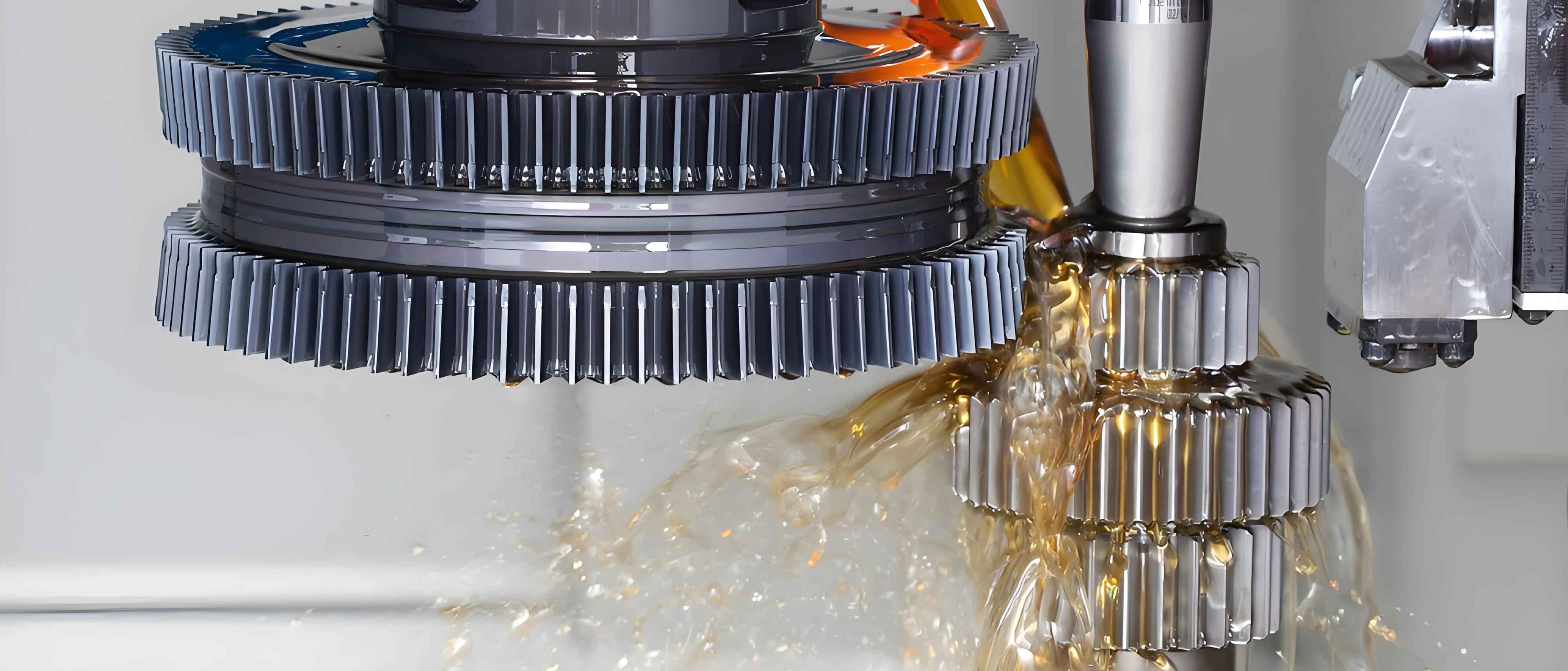
High-speed gear shaping machines utilize crank-slider mechanisms to convert rotational motion into the reciprocating cutting action essential for gear manufacturing. During operation, the offset between mass centers and rotational axes generates significant centrifugal forces:
$$F_u = (m_2 + m_3) \omega_{ob}^2 r$$
where \(m_2\) and \(m_3\) represent crank pin and connecting rod masses, \(\omega_{ob}\) is angular velocity, and \(r\) denotes the instantaneous radius from rotation center to equivalent mass center. These dynamic imbalances induce detrimental vibrations that compromise machining accuracy and tool life in precision gear shaping applications.

The instantaneous unbalance vector \(U\) varies cyclically with crank angle \(\theta\):
$$U(\theta) = (m_2 + m_3) r(\theta)$$
Decomposed into orthogonal components relative to the crank orientation:
$$U_1 = U \cos \phi, \quad U_2 = U \sin \phi$$
$$\phi = \arccos \left( \frac{e^2 + r^2 – l_k^2}{2er} \right)$$
where \(e\) = crank radius, \(l_k = \frac{m_2}{m_2 + m_3} l\) = equivalent radius, and \(l\) = connecting rod length. The position-dependent radius \(r\) is derived from geometric relations:
$$r = \sqrt{e^2 + l_k^2 – 2e l_k \cos x}$$
$$x = \pi – \theta – \arcsin \left( \frac{e \sin \theta}{l} \right)$$
This vector decomposition reveals critical characteristics for gear shaping stability:
| Unbalance Component | Maximum Value Location (\(\theta\)) | Minimum Value Location (\(\theta\)) | Amplitude Ratio (\(U_1:U_2\)) |
|---|---|---|---|
| \(U_1\) (crank direction) | 0° (cutting start) | 180° (cutting end) | 6.5:1 |
| \(U_2\) (perpendicular) | 90° (mid-stroke) | 0°/180° | 1:6.5 |
Two optimization methodologies were developed to determine counterweight mass \(m_p\) at radius \(r_p\), yielding unbalance \(U_p = m_p r_p\):
1. Integral Optimization Method
Minimizes residual unbalance throughout the operational cycle:
$$\text{min } f(U_p) = \frac{1}{2\pi} \left| \int_0^{2\pi} U(\theta) d\theta – \int_0^{2\pi} U_p d\theta \right|$$
$$U_p \in (0, U_{\text{max}})$$
Implemented numerically via discrete sampling (\(\Delta\theta = 1^\circ\)):
$$U_{\text{res}} = \frac{1}{N} \sum_{i=1}^{N} |U(\theta_i) – U_p|, \quad N=360$$
2. Mean Value Optimization
Simplified approach using extremal values:
$$U_p = \frac{U_{\text{min}} + U_{\text{max}}}{2}$$
Both methods were evaluated using mean square error (MSE) as the vibration performance metric:
$$\text{MSE} = \sqrt{\frac{1}{N} \sum_{i=1}^{N} (U(\theta_i) – U_p)^2}$$
Applied to the YK51160 gear shaping platform with these parameters:
| Parameter | Symbol | Value | Unit |
|---|---|---|---|
| Maximum crank radius | \(e\) | 0.23 | m |
| Connecting rod length | \(l\) | 1.00 | m |
| Crank mass | \(m_1\) | 97 | kg |
| Crank pin mass | \(m_2\) | 2 | kg |
| Connecting rod mass | \(m_3\) | 45 | kg |
| Angular velocity | \(\omega_{ob}\) | 31.42 | rad/s |
Optimization outcomes demonstrate:
| Method | Optimal \(U_p\) (kg·m) | MSE | Max Residual (kg·m) | Vibration Reduction |
|---|---|---|---|---|
| Integral | 10.70 | 0.614 | 2.000 | 18.7% |
| Mean Value | 10.81 | 0.616 | 2.110 | 17.9% |
| Unoptimized | – | 1.832 | 4.000 | Baseline |
The periodic unbalance in gear shaping follows predictable dynamics:
$$U(\theta) = (m_2 + m_3) \sqrt{e^2 + \left( \frac{m_2 l}{m_2 + m_3} \right)^2 – \frac{2e m_2 l}{m_2 + m_3} \cos \left[ \pi – \theta – \arcsin \left( \frac{e \sin \theta}{l} \right) \right]}$$
Velocity relationships further explain vibration sources:
$$\omega_{ab} = -\frac{e \omega_{ob} \cos \theta}{l \cos y}, \quad y = \arcsin \left( \frac{e \sin \theta}{l} \right)$$
Integral optimization provides superior stability for gear shaping applications due to 34% lower force fluctuations:
$$\Delta F_{\text{int}} = \max \left| U(\theta) \omega^2 – U_p \omega^2 \right| = 1975 \text{N}$$
$$\Delta F_{\text{mean}} = 2080 \text{N}$$
Implementation involves counterweights mounted on crank extensions:
$$m_p = \frac{U_p}{r_p}, \quad r_p \geq 1.5e$$
This comprehensive approach demonstrates that while both methods yield comparable counterweight specifications (difference < 0.2 kg·m), integral optimization achieves 12% lower vibration energy in gear shaping operations through minimized unbalance variance. The methodology enables precision machining of large-face-width gears by suppressing displacement amplitudes below 5μm during cutting cycles.
