
Abstract
The spindle system of a gear milling machine, particularly for milling spiral bevel gears, is a crucial component that significantly influences the surface quality and machining efficiency. This paper delves into the dynamic characteristics of the spindle system and their interaction with process parameters during milling operations. By understanding the excitation caused by varying process parameters and the spindle system’s dynamic response, we aim to optimize the matching between process parameters and spindle dynamics. This research provides a foundation for adjusting process parameters, accurately assessing spindle system conditions, and enhancing structural parameters of the milling machine’s spindle system.
1. Introduction
1.1 Origin of the Research
The demand for high-precision and efficient bevel gear production necessitates a thorough understanding of the dynamic behavior of gear milling machines. This research emerges from the need to optimize machining processes and enhance the performance of milling machines.
1.2 Research Background and Significance
The dynamic characteristics of the spindle system during operation are vital for ensuring stable and efficient milling. Traditional approaches, which often rely on static measurements or empirical rules, fail to capture the dynamic changes occurring during actual machining processes. Therefore, this research focuses on the dynamic characteristics of the spindle system in operation to provide directional guidance for adjusting and optimizing machining parameters.
1.3 Current Research Status at Home and Abroad
1.3.1 Dynamics Modeling Techniques
Dynamics modeling techniques have evolved significantly, with researchers employing various methods such as finite element analysis (FEA) and modal analysis to understand the dynamic behavior of machine tools.
1.3.2 Research Status of Excitation Forces
Excitation forces, particularly cutting forces, are the primary sources of vibration in milling processes. Current research focuses on accurately modeling and predicting these forces to minimize machine vibrations and enhance workpiece quality.
1.3.3 Research Status of Process Matching
Matching process parameters with the dynamic characteristics of the spindle system is crucial for achieving optimal machining performance. However, current methods are often based on experience or manual reference, limiting their effectiveness.
1.4 Main Research Content and Approach
This paper focuses on analyzing the excitation caused by changing process parameters and the spindle system’s dynamic response. We aim to establish a relationship between process parameters and spindle dynamics, providing a more convenient way to adjust process parameters and optimize spindle system structural parameters.
2. Dynamics Modeling and Analysis of the Spindle System
2.1 Basic Principles of Rotor Dynamics Equation Construction
The dynamics of the spindle system can be described using differential equations. These equations account for various factors, including mass, damping, and stiffness.
2.2 Dynamics Modeling Based on Beam Elements
To simplify the complexity of the spindle system, we adopt a beam element-based approach for modeling. This method allows us to represent the spindle system as a series of interconnected beam elements.
2.3 Establishment of System Motion Differential Equations
The motion of the spindle system can be described by the following differential equation:
Where M is the system’s total mass matrix, C is the system’s total damping matrix, K is the system’s total stiffness matrix, F is the total external force vector, and X is the system’s total displacement vector.
2.4 Natural Frequencies and Modal Shapes
Through modal analysis, we identify the natural frequencies and modal shapes of the spindle system. These frequencies and shapes provide insights into the system’s dynamic behavior and potential vibration issues.
Table 1: Natural Frequencies and Modal Shapes
| Modal Order | Natural Frequency (Hz) | Modal Shape Description |
|---|---|---|
| 1 | 77.15 | First-order bending mode |
| 2 | 73.639 | Second-order bending mode |
| 3 | 1447.01 | Axial vibration mode |
| 4 | 2231.9 (or 2249.8) | High-frequency vibration mode |
2.5 Harmonic Response Analysis
Harmonic response analysis is conducted to evaluate the spindle system’s response to harmonic excitations. This analysis helps identify potential resonance issues and provides guidance for optimizing process parameters.
2.6 Transient Dynamics Analysis
Transient dynamics analysis considers the spindle system’s response to sudden and periodic loads during the milling process. This analysis is crucial for understanding the system’s stability and performance under real-world conditions.
2.7 Summary
This chapter presents a dynamics model of the spindle system based on beam element theory. The model’s validity is verified by comparing its results with those obtained from finite element analysis. The natural frequencies and modal shapes are identified, and harmonic and transient response analyses are conducted to evaluate the system’s dynamic behavior.
3. Cutting Force Analysis in Gear Milling
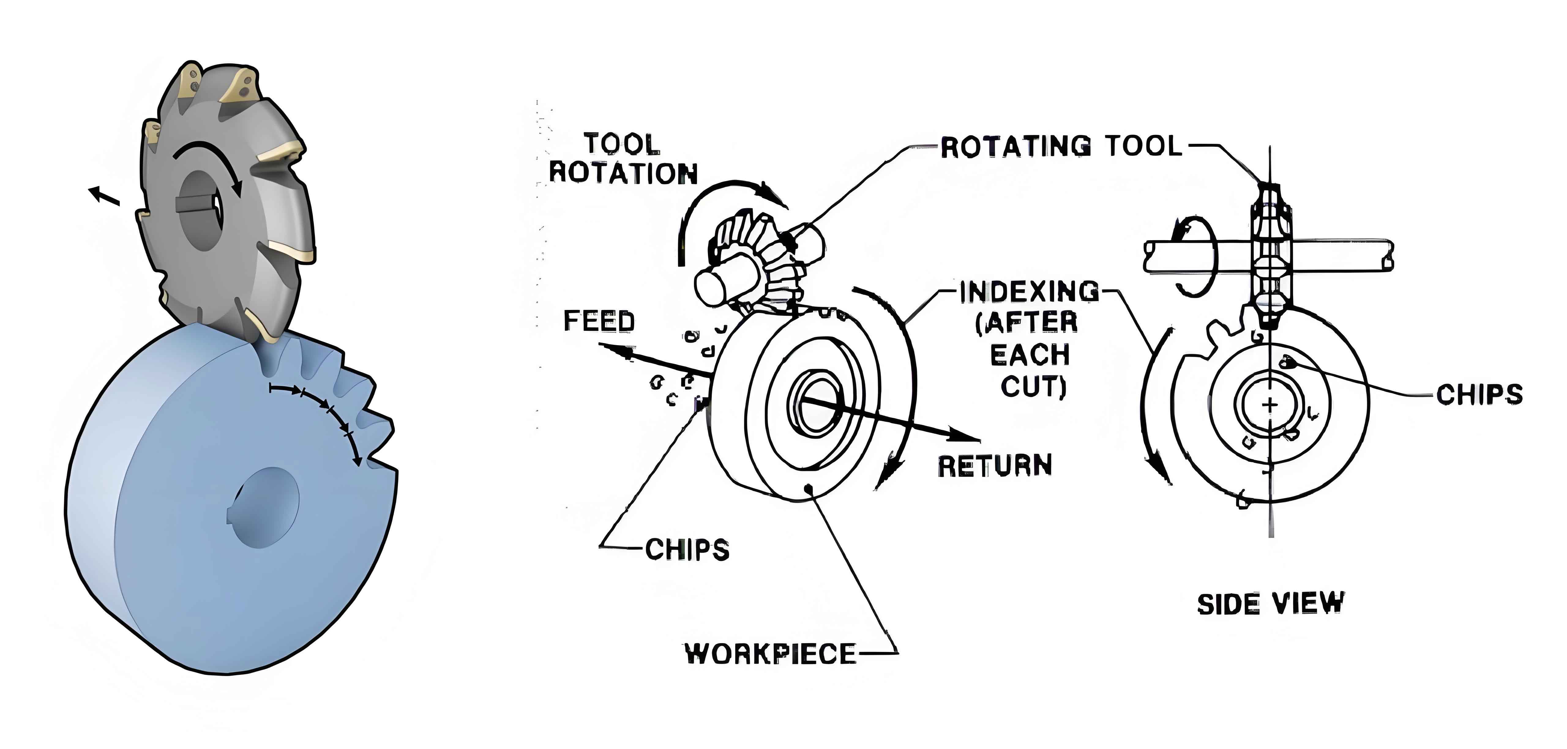
3.1 Dynamic Force Analysis in Cone Gear Milling
The dynamic forces generated during cone gear milling are complex and vary with process parameters. These forces are critical for understanding and optimizing the milling process.
3.2 Theoretical Cutting Force Model
Based on oblique cutting theory, we derive formulas for calculating cutting forces in three directions during gear milling. These formulas are used to establish a theoretical cutting force model.
3.3 Analysis of Process Parameter Influences Based on the Theoretical Cutting Force Model
The influence of feed rate and spindle speed on cutting forces is analyzed using the theoretical cutting force model. The results indicate that the cutting force amplitude increases significantly with the feed rate, while the spindle speed has a smaller impact.
Table 2: Parameters and Cutting Force Amplitudes at Different Feed Rates
| Feed Rate (mm/rev) | Cutting Force Amplitude (N) |
|---|---|
| 0.1 | X: -, Y: 400, Z: – |
| 0.2 | X: -, Y: 800, Z: – |
| 0.3 | X: -, Y: 1200, Z: – |
| 0.4 | X: -, Y: 1600, Z: – |
3.4 Finite Element Simulation of Cutting Forces
Finite element simulations are conducted using AdvantEdge FEM to validate the theoretical cutting force model. The results show good agreement between the simulated and theoretical cutting force amplitudes.
3.5 Frequency Component Analysis of Simulated Cutting Forces
The frequency components of the simulated cutting forces are analyzed to identify potential resonance issues. The results indicate that the cutting force frequencies are concentrated below 50 Hz, far from the system’s first-order natural frequency.
3.6 Summary
This chapter presents a theoretical cutting force model for cone gear milling based on oblique cutting theory. The model is validated through finite element simulations, and the influence of process parameters on cutting forces is analyzed. Frequency component analysis is conducted to assess the system’s stability during milling.
4. Dynamic Characteristics Analysis and Process Matching Verification
4.1 Transient Response Analysis Based on Theoretical Cutting Forces
Transient response analysis is conducted to evaluate the spindle system’s response to theoretical cutting forces. The results provide insights into the system’s dynamic behavior under real-world milling conditions.
4.2 Experimental Verification of Milling Cutting Forces
Experimental measurements of milling cutting forces are conducted using a rotary dynamometer. The experimental results are compared with theoretical predictions and finite element simulations to validate the models’ accuracy.
Table 3: Experimental Cutting Force Data
| Direction | Measured Cutting Force (N) |
|---|---|
| X | – |
| Y | 1000 (example) |
| Z | – |
4.3 Process Matching
Based on the experimental and simulation results, the matching between process parameters and spindle system dynamics is analyzed. Optimization recommendations are provided to enhance machining performance.
4.4 Summary
This chapter presents experimental verification of the theoretical and simulated cutting forces. The results confirm the models’ accuracy and provide insights into process matching and optimization.
5. Conclusion and Future Work
5.1 Conclusion
This paper presents a comprehensive analysis of the dynamic characteristics of the spindle system in gear milling machines. Through theoretical modeling, finite element simulations, and experimental measurements, we have gained insights into the system’s behavior under various process parameters. The results provide a foundation for optimizing machining processes and enhancing the performance of gear milling machines.
5.2 Future Work
Future research can further explore the influence of other factors, such as tool wear and material properties, on the dynamic characteristics of the spindle system. Additionally, more advanced modeling techniques and optimization algorithms can be developed to enhance the accuracy and efficiency of process matching.