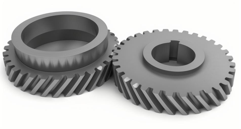
Helical gears play a critical role in power transmission systems due to their superior load-bearing capacity and smooth engagement characteristics. This study investigates how profile shift modifications affect time-varying mesh stiffness (TVMS) and dynamic responses in helical gear systems through analytical modeling and dynamic simulations.
1. Modified Helical Gear Geometry
The geometric relationships of profile-shifted helical gears differ from standard designs through altered addendum, dedendum, and pressure angle. Key modified parameters include:
$$h_{ai} = (h_a^* + x_{ni} – \Delta y_n)m_n$$
$$h_{fi} = (h_a^* + c^* – x_{ni})m_n$$
$$a’ = \frac{m_t(z_1 + z_2)\cos\alpha_{0t}}{2\cos\alpha’_t}$$
$$\text{inv}\alpha’_t = \frac{2\tan\alpha_{0t}(x_{mc1} + x_{mc2})}{z_1 + z_2} + \text{inv}\alpha_{0t}$$
where $x_{mc}$ represents the profile shift coefficient and $\Delta y_n$ denotes the addendum reduction factor.
2. Time-Varying Mesh Stiffness Calculation
The comprehensive mesh stiffness of helical gears combines multiple deformation components:
| Stiffness Component | Formula |
|---|---|
| Hertzian Contact | $$k_h = \frac{\pi EL}{4(1-\nu^2)}$$ |
| Bending | $$k_b = \sum_{i=1}^N \left(\int_{\alpha_1}^{\alpha_2} \frac{3\cos\alpha[1+\cos\alpha_1(\alpha_2-\alpha)\sin\alpha]^2}{2E[\sin\alpha + (\alpha_2-\alpha)\cos\alpha]^3}d\alpha\right)^{-1}$$ |
| Shear | $$k_s = \sum_{i=1}^N \left(\int_{\alpha_1}^{\alpha_2} \frac{1.2(1+\nu)\cos\alpha\cos^2\alpha_1}{E[\sin\alpha + (\alpha_2-\alpha)\cos\alpha]}d\alpha\right)^{-1}$$ |
The total mesh stiffness varies with contact ratio $\varepsilon$:
$$k_{total} =
\begin{cases}
\sum_{i=1}^2 \left(\frac{1}{k_{h,i}^{-1}+k_{b,i}^{-1}+k_{s,i}^{-1}}\right)^{-1}, & \varepsilon \in (2,3) \\
\sum_{i=1}^3 \left(\frac{1}{k_{h,i}^{-1}+k_{b,i}^{-1}+k_{s,i}^{-1}}\right)^{-1}, & \varepsilon \geq 3
\end{cases}$$
3. Dynamic Modeling of Helical Gear Systems
An 8-DOF dynamic model considers translational and rotational motions:
$$L = \frac{1}{2}\dot{\mathbf{q}}^T\mathbf{M}\dot{\mathbf{q}} – \frac{1}{2}\mathbf{q}^T\mathbf{K}\mathbf{q}$$
$$D = \frac{1}{2}\dot{\mathbf{q}}^T\mathbf{C}\dot{\mathbf{q}}$$
Governing equations of motion include:
$$m_p\ddot{x}_p + c_{bx}\dot{x}_p + k_{bx}x_p = -F_{mx} – F_f\sin\alpha$$
$$I_p\ddot{\theta}_p = F_{my}R_{bp} – T_p$$
$$m_g\ddot{x}_g + c_{bx}\dot{x}_g + k_{bx}x_g = F_{mx} + F_f\sin\alpha$$
4. Profile Shift Effects on Dynamic Behavior
Five modification cases were analyzed:
| Case | Pinion Shift | Gear Shift |
|---|---|---|
| 1 | 0.1 | 0.3 |
| 2 | -0.1 | 0.3 |
| 3 | 0 | 0 |
| 4 | 0.1 | -0.3 |
| 5 | -0.1 | -0.3 |
Key findings include:
- Positive profile shifts reduce TVMS by 12-18% compared to standard gears
- Negative shifts increase TVMS by 15-22%
- Dynamic transmission error decreases 8-14% with positive shifts
$$X_{RMS} = \sqrt{\frac{1}{N}\sum_{i=1}^N x_i^2}$$
$$X_{KV} = \frac{1}{N}\sum_{i=1}^N \left(\frac{x_i-\bar{x}}{\sigma}\right)^4$$
5. Frequency Domain Characteristics
Profile shift modifications significantly alter frequency responses:
- Positive shifts reduce mesh frequency amplitude by 6-9 dB
- Negative shifts increase sideband energy by 10-15%
- Envelope modulation period decreases 18-25% with positive shifts
The helical gear system demonstrates strong coupling between time-varying stiffness and dynamic responses, where:
$$F_m = k_m e_{DTE} + c_m \dot{e}_{DTE}$$
$$e_{DTE} = R_{bp}\theta_p – R_{bg}\theta_g + (x_p-x_g)\cos\alpha + (y_p-y_g)\sin\alpha$$
6. Design Recommendations
Based on the analysis:
- Use positive profile shifts (xΣ > 0) for vibration reduction
- Apply negative shifts (xΣ < 0) when increased load capacity is critical
- Optimize shift coefficients within xΣ ∈ [-0.4, 0.4] to avoid undercutting
This research provides fundamental insights for optimizing helical gear performance through strategic profile shift modifications, balancing dynamic behavior and load capacity requirements.
