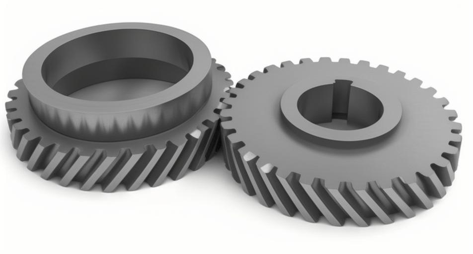
Helical gear systems with double inputs and a single output (DI-SO) are critical components in marine propulsion systems. Their asymmetric load distribution often leads to nonlinear instability, which significantly impacts operational safety. This study investigates the vibration characteristics of DI-SO helical gear systems under unsymmetrical load parameters, focusing on bifurcation behaviors, time-frequency responses, and phase-space trajectories.
1. Dynamic Modeling of DI-SO Helical Gear System
The torsional vibration model of the DI-SO helical gear system includes two driving gears (p, q), one driven gear (g), and an inertial flywheel. The governing equations are derived using Newton’s second law:
$$
\begin{cases}
J_p \ddot{\theta}_p + k_1(t) f(r_{bp}\theta_p – r_{bg}\theta_g – e_1(t)) + c_{m1}(r_{bp}\dot{\theta}_p – r_{bg}\dot{\theta}_g) = T_p \\
J_g \ddot{\theta}_g – k_1(t) f(r_{bp}\theta_p – r_{bg}\theta_g – e_1(t)) + k_2(t) f(r_{bg}\theta_g – r_{bq}\theta_q – e_2(t)) + \cdots = T_g \\
J_q \ddot{\theta}_q – k_2(t) f(r_{bg}\theta_g – r_{bq}\theta_q – e_2(t)) – c_{m2}(r_{bg}\dot{\theta}_g – r_{bq}\dot{\theta}_q) = T_q
\end{cases}
$$
where \( f(x) \) represents the nonlinear backlash function, \( k_r(t) \) denotes time-varying meshing stiffness, and \( c_{mr} \) is the damping coefficient.
2. Mathematical Description of System Parameters
2.1 Time-Varying Meshing Stiffness
The meshing stiffness of helical gears combines bending, shear, axial compression, and Hertzian contact stiffness. For a single tooth pair:
$$
k_{\text{single}} = \left( \frac{1}{k_h} + \sum_{i=1}^2 \left( \frac{1}{k_{bi}} + \frac{1}{k_{si}} + \frac{1}{k_{ai}} + \frac{1}{k_{fi}} \right) \right)^{-1}
$$
Key parameters for helical gear pairs are summarized below:
| Parameter | Value |
|---|---|
| Module (mm) | 4 |
| Pressure Angle (°) | 20 |
| Helix Angle (°) | 10 |
| Face Width (mm) | 50 |
| Total Contact Ratio | 2.45 |
2.2 Phase Difference in Meshing Stiffness
The phase difference \( \Delta\phi \) between left and right gear pairs is calculated as:
$$
\Delta\phi = \omega_e \cdot \frac{2\pi\delta}{z_1\omega_1}
$$
where \( \delta \) represents the fractional part of the tooth engagement difference.
2.3 Nonlinear Backlash Function
A 7th-order polynomial approximates the backlash nonlinearity:
$$
g(x) = 0.0017x^7 – 0.0366x^5 + 0.2833x^3 – 0.1555x
$$
3. Numerical Analysis of Vibration Characteristics
3.1 Light-Load Conditions (\( f_1 = 0.1 \))
The bifurcation diagrams reveal distinct dynamic behaviors:
| Load Ratio (λ) | p-g Pair | q-g Pair |
|---|---|---|
| 0.0–0.57 | Quasi-periodic | Chaotic |
| 0.57–1.0 | Period-1 | Period-1 |
3.2 Heavy-Load Conditions (\( f_1 = 0.5 \))
Increased loads stabilize the system:
$$
\text{Max}(u) \propto f_1, \quad \text{Min}(v) \propto \lambda
$$
Critical load ratios for stability transitions decrease with higher \( f_1 \).
3.3 Coupled Effects of Load Magnitude and Ratio
Key observations include:
- Chaotic regions shrink by 63% when \( f_1 \) increases from 0.1 to 0.5
- Optimal stability occurs at \( \lambda > 0.57 \) and \( f_1 > 0.3 \)
4. Conclusions
This investigation demonstrates that DI-SO helical gear systems exhibit complex nonlinear behaviors under asymmetric loads. Increasing either the load ratio (\( \lambda \)) or absolute load magnitude (\( f_1 \)) significantly reduces instability regions. The 7th-order polynomial approximation effectively captures backlash nonlinearity, while phase-adjusted stiffness modeling enables accurate prediction of meshing dynamics. These findings provide critical insights for designing marine propulsion systems with enhanced stability.
