
Based on the introduction of the corresponding mathematical model and application scenarios proposed for the dynamic physical model of gear transmission system, in order to intuitively study and analyze the dynamic response characteristics of gear transmission system under tooth surface fatigue pitting, a six degree of freedom single-stage gear transmission dynamic model is established as shown in Fig. 1. In the model, the prime mover, gear pair and load machine are mainly considered, and the design is completed All the idealized assumptions are to reduce the influence factors of the system and improve the response characteristics of the system under the action of fatigue pitting. This simplified model is used to study and analyze the effect of tooth crack on the dynamic characteristics of the system.

According to the topological diagram of the dynamic model shown in Figure 1, the simplified gear system mainly includes the transmission system of prime mover, gear pair and load machine, the torsional stiffness and damping effect of the output shaft of prime mover and input shaft of load machine, the elastic support stiffness and damping effect of the driving / driven gear, and the time-varying meshing stiffness and damping effect between gear pairs. In order to reduce the complexity of analysis parameters and equations, the x-axis of the system is defined as the meshing line (Loa) along the gear pair, and the Y-axis of the system is defined as the non meshing line (oloa). According to the vibration characteristics of the prime mover, the displacement and torsional effect of the gears can be divided into two parts. Because of the setting of the system coordinates between the gear pairs, when the friction effect between the gear pairs is not considered in the system, there is no corresponding load component along the oloa direction between the gear pairs, and the displacement vibration in the X and Y directions is mutually independent, so the displacement vibration effect along the oloa direction can not be considered under the friction free action.
According to the space geometry and motion relationship among prime mover, gear pair and load, the corresponding differential vibration equation of the system can be listed by using load transfer law and Newton’s law. In order to eliminate the influence of the weight of the gear itself, the vibration equation of the gear along the loa action line is analyzed by its static equilibrium state.
When the system is in stable operation under external excitation, the differential equations of motion of the gear system can be described as follows:
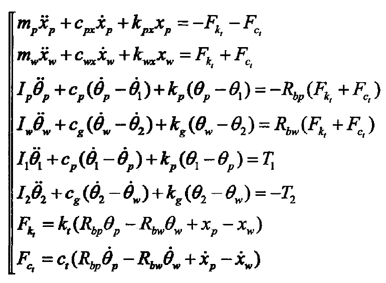
Where:
IP, IW, I1 and I2 – the moment of inertia of driving gear, driven gear, prime mover and loader in turn;
MP, MW – mass of driving gear and driven gear;
KPX, kwx – support stiffness of driving gear and driven gear along X direction;
CPX and CWX are the supporting damping of driving gear and driven gear along X direction;
KP and kg are torsional stiffness of prime mover input shaft and load output shaft;
CP, CG – torsional damping of prime mover input shaft and load output shaft;
FK., FC, one is the elastic deformation force and damping force of gear meshing;
RBP, RBW are the base circle radius of driving gear and driven gear;
KT , CT- are the meshing stiffness and damping of gear pair;
θ 1, θ 2, θ P and θ W are the angular displacement of prime mover, loader, driving gear and follower gear in turn;
XP, XW – displacement of driving gear and driven gear along the direction of Loa action line.