1. Parameters of complete machine and gear
| Cylinder diameter/mm | Stroke/mm | Number of cylinders | Rated power/kW | Maximum torque / (N · m) | Rated speed/(r · min ^ – 1) |
| 150 | 185 | 10 | 1700 | 7000 | 2500 |
The main technical parameters of a large bore diesel engine are shown in Table 1, and the main timing gear parameters of the gear transmission system are shown in Table 2.
| Components | Number of teeth | Modulus/mm | Pressure angle / (°) | Helical angle / (°) | Tooth width/mm |
| Crankshaft gear | 48 | 2 | 20 | 15 | 54 |
| Camshaft gear | 96 | 2 | 20 | 15 | 22 |
| Injection pump idler | 31 | 2 | 20 | 15 | 20 |
| Injection pump gear | 26 | 2 | 20 | 15 | 20 |
2. Modeling
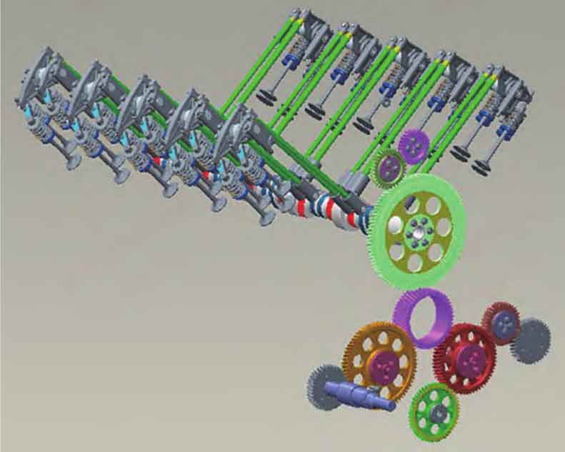
The gear system and valve train model of a large bore diesel engine is shown in Figure 1. In the dynamic analysis, the component is simplified as the equivalent concentrated mass. The equivalent masses are connected by massless spring and damping. The lumped mass-spring model in vibration mechanics is used for analysis. Each mass is represented by 1 degree of freedom.
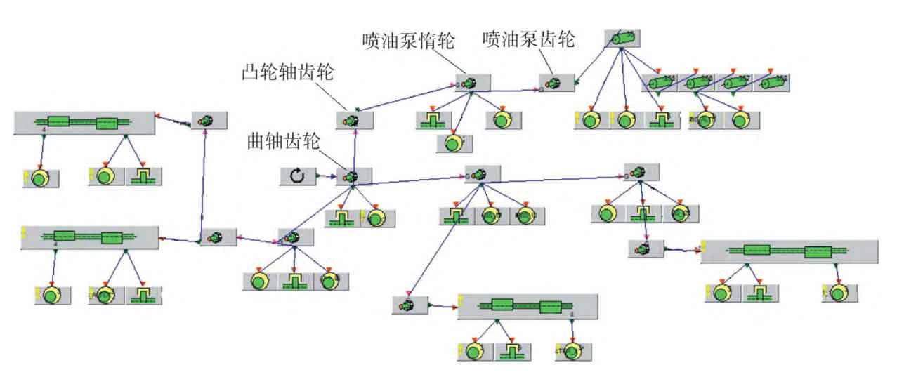
According to this method, the gear and valve train system is simplified into a multi-degree-of-freedom vibration model. Considering the influence of support stiffness, load torque fluctuation, cylinder pressure, intake and exhaust fluctuation, clearance and other factors, the multi-degree-of-freedom dynamic calculation model of the gear system is established through the software EXCITETimingDrive, as shown in Figure 2.
3. Relevant parameters
| Components | Equivalent mass/kg | Stiffness/(kN · mm ^ – 1) |
| Lower part of push rod | 0.587 | 107.1 |
| Upper part of push rod | 0.179 | 107.1 |
| Rocker arm | 0.392 | 56.6 |
| Valve bridge | 0.153 | 150.5 |
| Valve stem | 0.112 | 257.0 |
| Valve face | 0.201 | 188.2 |
Relevant parameters of valve train and gear system required for dynamic calculation are obtained through software measurement and finite element calculation, as shown in Table 3 and Table 4.
| Components | Mass/kg | Rotational inertia/(kg · mm ^ 2) | Bending inertia/(kg · mm ^ 2) |
| Crankshaft gear | 2.48 | 12 128 | 6765 |
| Camshaft gear | 5.68 | 84 224 | 42295 |
| Injection pump idler | 0.93 | 1 515 | 803 |
| Injection pump gear | 0.79 | 861 | 482 |
4. Boundary conditions
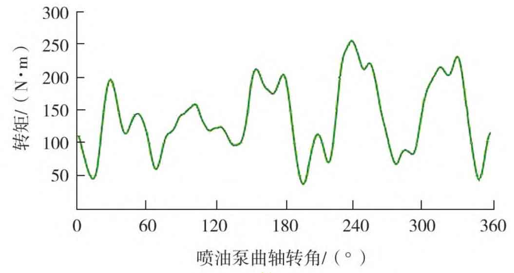
The boundary conditions of gear dynamics calculation mainly include: 1) The crankshaft speed fluctuation adopts the fluctuation curve of dynamics calculation, and studies its influence on gear dynamics characteristics as the research object; 2) The cylinder pressure curve and inlet and outlet pressure curve of the valve train dynamics model are obtained through thermodynamic calculation; 3) The load of the gear system includes the torque of the fuel injection pump, fresh water pump, sea water pump, oil pump and generator. The torque curve of fuel injection pump at rated speed is shown in Figure 3. The torque of seawater pump, fresh water pump, oil pump and generator are 46 0、58. 0、84. 4、22. 4 N·m。