
The internal excitation of planetary gear train is complex, and the power transmission path changes with the turnover of planetary gear. The planetary gear train of the cutting transmission system studied in this paper has a compact structure compared with the fixed shaft gear. Therefore, the dynamic response characteristics of the multi-stage fixed shaft gear under the deformation condition of the transmission system are taken as the research focus of this paper to simplify the modeling of the planetary gear train and speed up the model solving speed. Kahraman established the pure torsional dynamic model of planetary gear train, and there are three improvements in this study
1) The generalized coordinate adopts angular displacement instead of vibration angular displacement, and the model includes the rigid body rotation of components, so the rotation speed of planetary gear system is determined by the load in real time, and there is no need to determine the working speed in advance;
2) The generalized coordinates are measured in the fixed coordinate system instead of the planetary carrier follow-up coordinate system, which is convenient for coupling with the fixed shaft gear and the roller;
3) At the same time, the forward and reverse rotation of the sun wheel are analyzed, and a unified mathematical model is established, so it can be used for different steering of the left and right rocker arms.
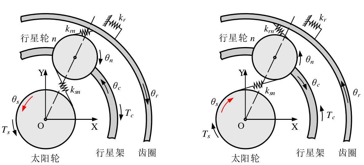
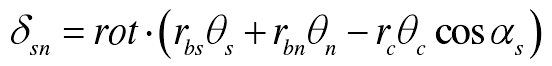
The pure torsional dynamic model of planetary gear train is shown in Figure 1. The angular displacement of each component in fixed coordinate system oxy is θ I (I = C, R, s, 1, 2,…) 、N)。 The inner ring gear is fixed, and the torsional stiffness of its support system is Kr; the sun gear is the input end, and the planet carrier is the output end; the sun gear rotates counterclockwise to be positive, rot = 1, and clockwise to be negative, rot = – 1 (right hand rule). Through kinematic analysis, the projection of the displacement of the sun gear relative to the nth planetary gear along the direction of the outer meshing line is as follows:
The projection of the displacement of the inner ring gear relative to the nth planetary gear along the direction of the internal meshing line is as follows:
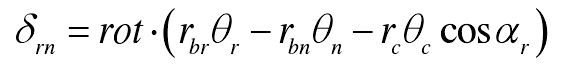
Where RBI (I = R, s, 1, 2,…) , n) is the radius of base circle of component I; RC is the radius of planet carrier; α s is the meshing angle of external meshing; α R is the meshing angle of internal meshing.