
Straight bevel gear transmission is an important power transmission system in automobile and aviation machinery. Its dynamic behavior directly affects the working stability and efficiency of power equipment. Some results have been obtained in the dynamic modeling, structural modal analysis and nonlinear vibration analysis of spiral bevel gear transmission.
For the straight bevel gear transmission system studied, in the process of straight bevel gear transmission, there will be dynamic meshing force in the normal direction between the tooth surfaces, which will be decomposed along the radial, tangential and axial directions. The forces in the three directions decomposed make the straight bevel gear transmission system vibrate, including torsional vibration, transverse vibration, axial vibration and torsional vibration generated by axial force. Ignoring the influence of the elastic deformation of the transmission shaft, support bearing and box on the meshing performance of the straight bevel gear system, the dynamic analysis model of the straight bevel gear transmission system is obtained by using the lumped parameter method, as shown in the figure.
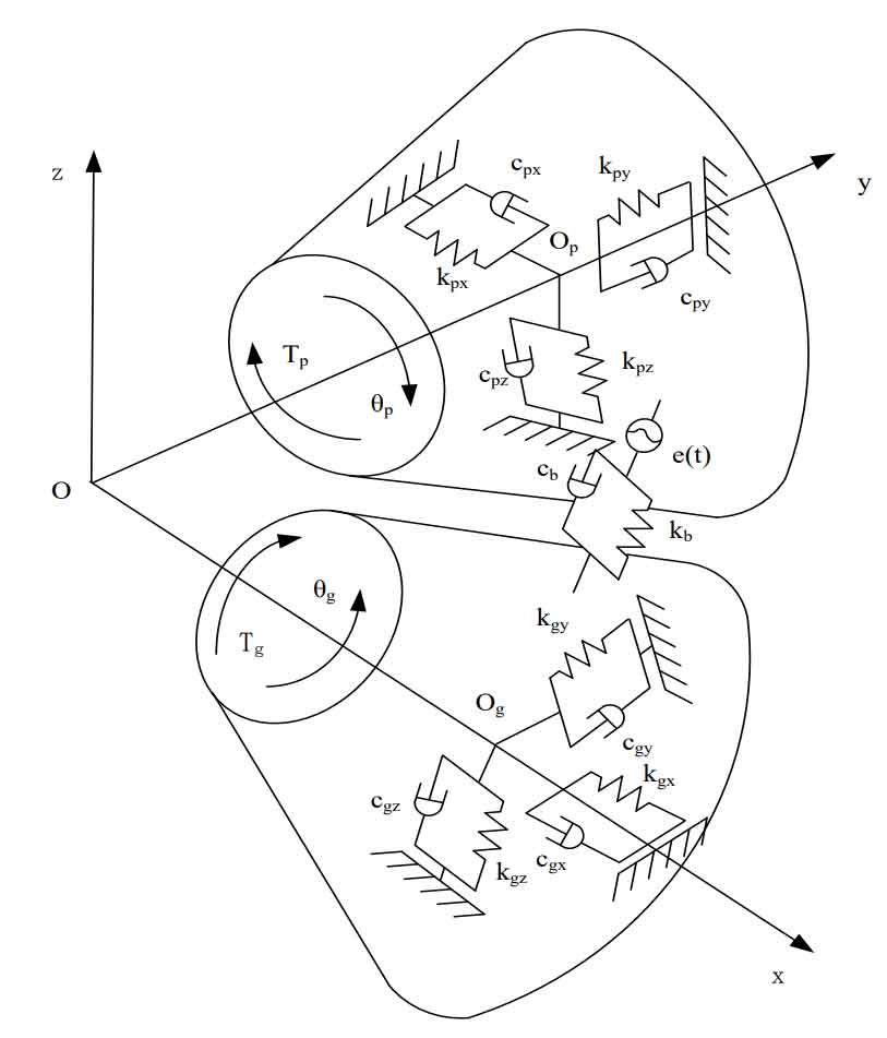
Let the included angle of the axes of the two straight bevel gears be 90 °, and the intersection of the axes when the two straight bevel gears are actually engaged is the origin. Create the coordinate system o-xyz. In the model, Kij and CJI respectively represent the meshing stiffness and meshing damping in the three coordinate directions, regardless of the tooth surface friction and torsional vibration. The vibration of the straight bevel gear transmission system mainly includes the transverse vibration along the X, y and Z directions Axial and meshing line torsion.
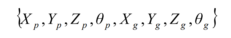
Suppose TP is the driving torque applied to the planetary gear P, TG is the resistance torque of the half shaft gear g, and the two straight bevel gears are rigid bodies, then the movement of the two straight bevel gear wheel bodies along the X, y and Z axes, the rotation of the wheel body with the gear shaft and the torsion during meshing are as follows:
The existence of various deformations and errors in the straight bevel gear transmission system changes the position of the node on the connecting line of the two straight bevel gears when the straight bevel gears mesh. The teeth cannot mesh normally, and the meshing point deviates along the normal direction, resulting in its relative displacement λ N is as follows:
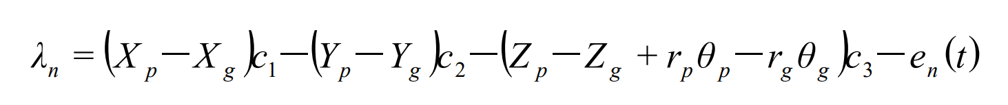
Where C1 = cos δ p sin α n, c2 = cos δ p cos α n , c3 = cos α n ; p δ Is the cone angle of planetary bevel gear pitch; α N is the normal pressure angle of straight bevel gear; RP and RG are the meshing point radius of straight bevel gear; En (T) is the normal static error of the gear pair.
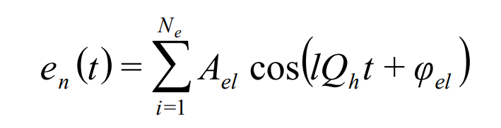
Where QH is the meshing frequency; AEL is the L-order harmonic amplitude of the error; φ El is the initial phase.
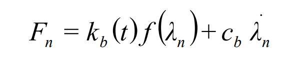
The normal dynamic load between teeth in the meshing process of straight bevel gear pair is:
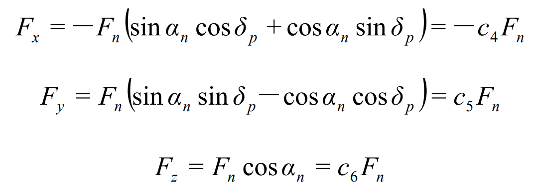
The normal dynamic load between gear teeth is decomposed along the three directions of X, y and Z axes, and the forces in the three directions are as follows:
Where KB (T) is time-varying meshing stiffness; CB is meshing damping; Km is the average meshing stiffness; f( λ n) Is the backlash.