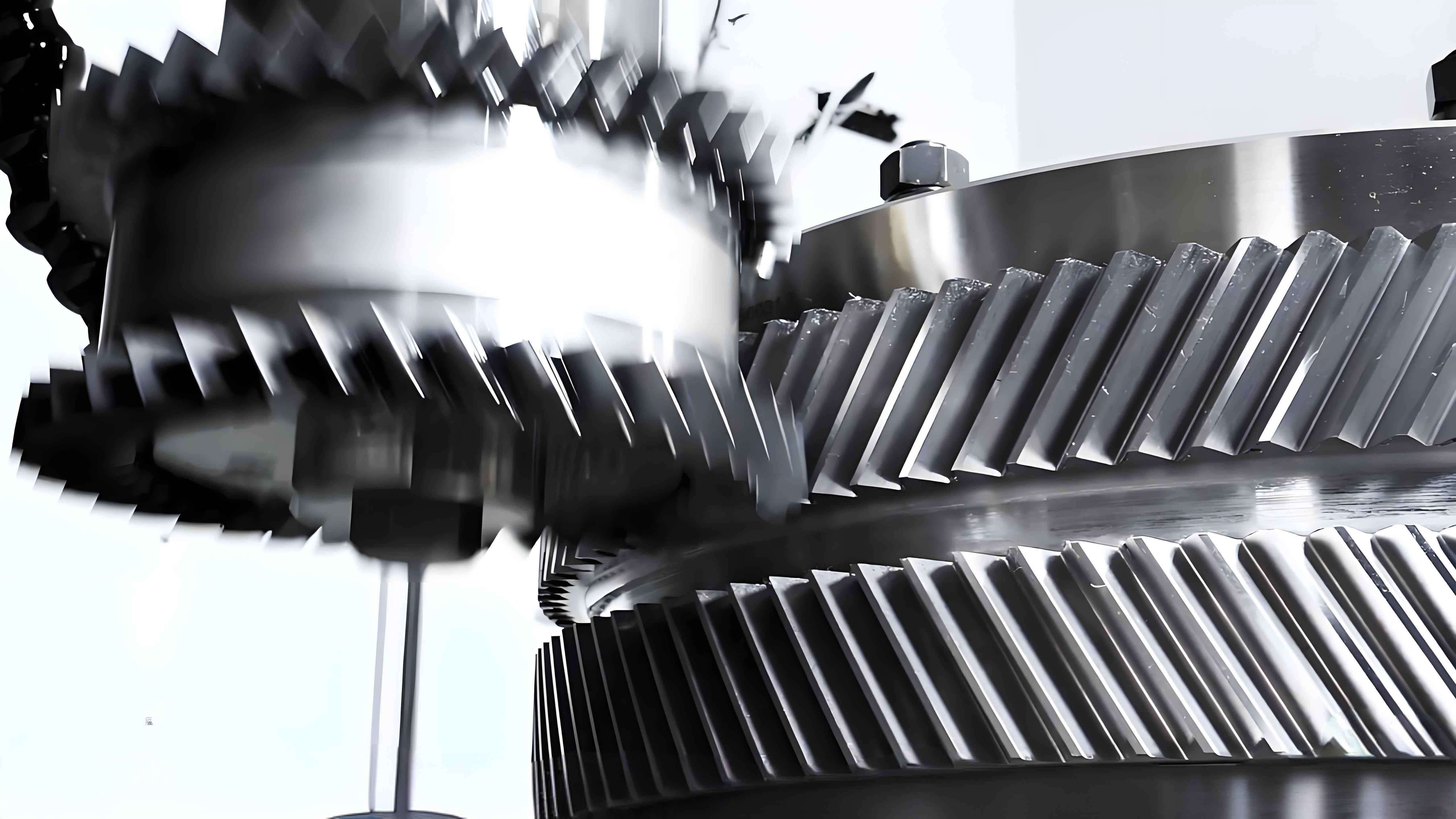
This paper investigates the dynamic behavior of herringbone gear transmission systems through multi-body dynamics modeling and experimental validation. A novel rigid-flexible coupling model incorporating gearbox-bearing-shaft interactions is developed to analyze vibration mechanisms under manufacturing/assembly errors.
1. Dynamic Modeling Methodology
The governing equations for herringbone gear dynamics consider both translational and rotational motions:
$$
\begin{bmatrix}
M
\end{bmatrix}
\ddot{x} +
\begin{bmatrix}
C
\end{bmatrix}
\dot{x} +
\begin{bmatrix}
K
\end{bmatrix}
x = \{P(t)\}
$$
Where $[M]$, $[C]$, and $[K]$ represent the mass, damping, and stiffness matrices respectively. The kinetic energy formulation for gear components includes both translational and rotational components:
$$
T = \frac{1}{2}m(\dot{x}^2 + \dot{y}^2 + \dot{z}^2) + \frac{1}{2}J_d(\dot{\theta}_x^2 + \dot{\theta}_y^2) + \frac{1}{2}J_p\dot{\theta}_z^2
$$
| Parameter | Value |
|---|---|
| Teeth Count (Z₁/Z₂) | 25/32 |
| Module (mm) | 25 |
| Helix Angle (°) | 26 |
| Pressure Angle (°) | 20 |

2. Error Impact Analysis
The study examines two critical error types in herringbone gear systems:
2.1 Axis Misalignment
The equivalent displacement due to axis tilt angle θ:
$$
\Delta L = \frac{w\theta}{2} \quad (w = \text{Gear width})
$$
2.2 Eccentricity Error
Eccentricity-induced displacement function:
$$
e(t) = e_0 \sin(\omega t + \phi) \quad (\omega = \text{Rotational frequency})
$$
| Condition | Meshing Freq. (Hz) | Peak Acceleration (mm/s²) |
|---|---|---|
| Normal | 250 | 1,207 |
| Axis Tilt (0.03°) | 250 + 7.81 | 1,433 |
| Eccentricity (0.2mm) | 250 + 26.91 | 1,444 |
3. Tooth Modification Effects
Crowning modification significantly reduces vibration levels:
$$
C_\beta = \frac{F_b^3}{48EI} \quad (C_\beta = \text{Crowning amount})
$$
| Modification | Vibration Reduction |
|---|---|
| 0.02mm Crowning | 15-18% |
4. Key Findings
- Herringbone gear systems exhibit unique 180° phase difference between left/right flank vibrations
- Eccentricity errors generate non-synchronous frequency components related to contact ratio:
$$
f_e = \frac{\varepsilon Z n}{60} \quad (\varepsilon = \text{Contact ratio})
$$ - Optimal crowning reduces meshing impact forces by 23-25%
5. Experimental Validation
Field measurements confirm the simulation accuracy with <5% deviation in dominant frequency components. The characteristic vibration spectrum shows excellent agreement between numerical predictions and actual gearbox measurements.
This comprehensive analysis provides critical insights for optimizing herringbone gear system design and maintenance strategies in heavy-duty industrial applications.
