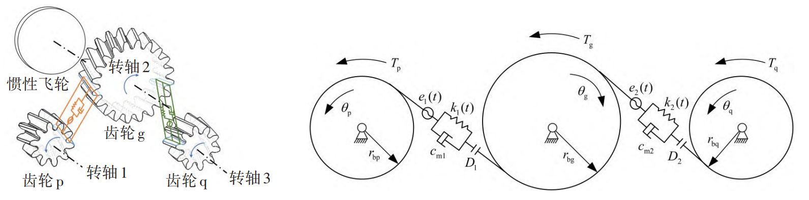
The physical model and simplified torsional vibration model of a rigid supported dual input single output helical gear system without considering the influence of the rotating shaft and bearings in motion are shown in the figure. The system consists of two power input helical gears (p, q), one power output helical gear (g), and an inertia flywheel, where shaft 1 is a high load input shaft and shaft 3 is a low load input shaft. Each helical gear is described by its base circle radius (rbp, rbg, and rbq). In the system, Tp, Tg, and Tq are the moments acting on each helical gear, θ p、 θ G and θ Q is the dynamic angular displacement of each helical gear, Jp and Jq are the rotational inertia of the two driving helical gears, Jf is the equivalent rotational inertia of the large gear and flywheel on the output shaft, er (((t) r=1,2) is the time-varying comprehensive transmission error of the two pairs of helical gears along the meshing line, cm (r=1,2) is the average meshing damping of the two pairs of gears, kr (((t) r=1,2) is the time-varying meshing stiffness of the two pairs of helical gears, D (r r=1,2) is half of the tooth side clearance between two pairs of helical gear pairs, β B is the helix angle of the base circle.
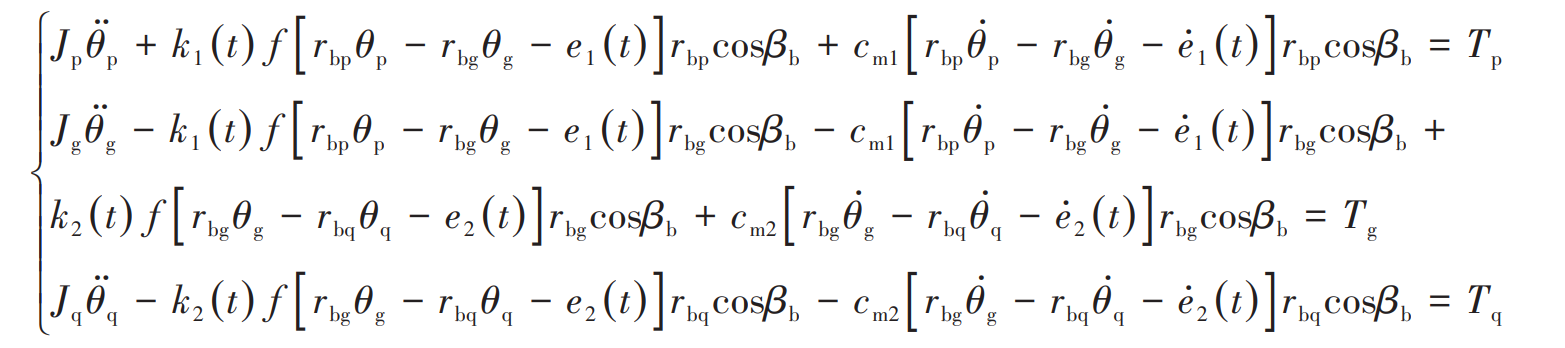
According to Newton’s second law of motion, establish the pure torsional dynamic equation of a dual input single output helical gear system: