
In modern mechanical transmissions, spiral bevel gears are critical components due to their high load capacity, smooth operation, and low sensitivity to installation errors. They are widely used in aerospace, automotive, and other high-performance applications. However, as operational speeds and power densities increase, the dynamic behavior of spiral bevel gears becomes a significant concern, directly impacting vibration, noise, and system reliability. Traditional design approaches often focus on static or quasi-static performance, neglecting the influence of time-varying parameters and system dynamics. In this work, I present a comprehensive methodology for optimizing the dynamic characteristics of spiral bevel gears using a genetic algorithm. By integrating a nonlinear dynamic model with an evolutionary optimization framework, I aim to minimize vibration responses through targeted tooth surface modifications, thereby enhancing the overall performance of gear transmission systems.
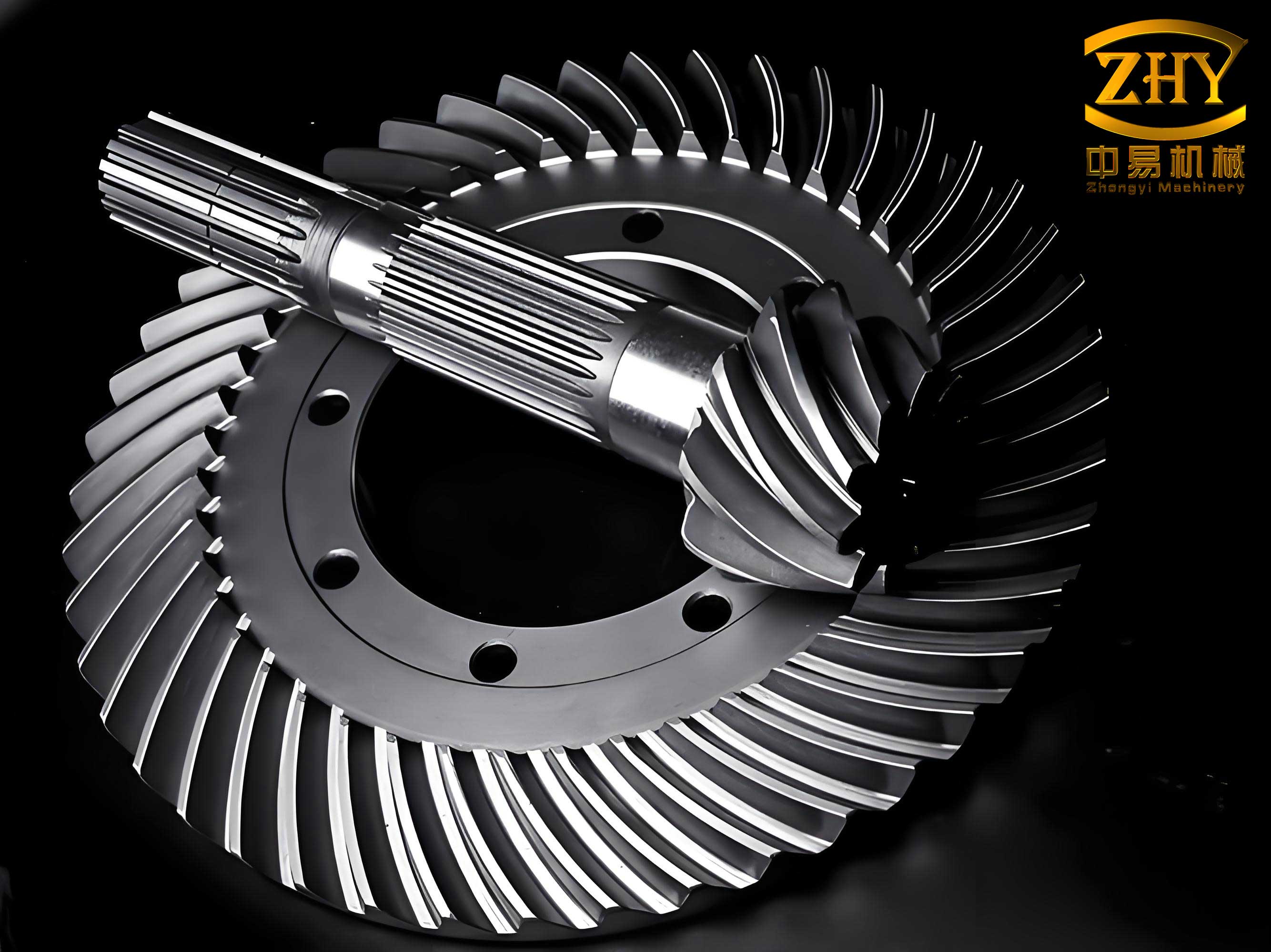
The optimization of spiral bevel gears requires a deep understanding of their dynamic behavior under operational conditions. Dynamic excitations in spiral bevel gears arise from factors such as time-varying mesh stiffness, geometric transmission errors, backlash, and nonlinear bearing supports. These factors can lead to excessive vibrations and noise, which are detrimental to system longevity and efficiency. Therefore, a robust dynamic model that captures these phenomena is essential for effective optimization. I developed an eight-degree-of-freedom (8-DOF) nonlinear dynamic model based on the lumped mass method, which accounts for bending, axial, and torsional vibrations in a three-dimensional space. This model serves as the foundation for evaluating the dynamic performance of spiral bevel gears and forms the basis for the optimization process.
The dynamic model considers the coupled vibrations of both the pinion and gear. The coordinate system is defined with the origin at the intersection of the pinion and gear axes. The pinion axis is aligned with the X-direction, the gear axis with the Y-direction, and the Z-direction is determined by the right-hand rule. The degrees of freedom include translational displacements in the X, Y, and Z directions and rotational displacements about the axes for both the pinion and gear. The relative displacement along the mesh line, which is crucial for calculating the dynamic mesh force, is derived from these displacements and includes contributions from geometric transmission errors. The equation for the normal relative displacement is given by:
$$ \lambda_n = (X_1 – X_2) c_X + (Y_1 – Y_2) c_Y + (Z_1 – Z_2) c_Z + \theta_1 r_{b1} – \theta_2 r_{b2} – e_n(t) $$
Here, \(X_1, Y_1, Z_1\) and \(X_2, Y_2, Z_2\) are the translational displacements of the pinion and gear, respectively; \(\theta_1\) and \(\theta_2\) are the angular displacements; \(c_X, c_Y, c_Z\) are direction cosines projecting the displacements onto the mesh normal direction; \(r_{b1}\) and \(r_{b2}\) are the base circle radii at the mid-face width; and \(e_n(t)\) is the geometric transmission error expressed as a Fourier series:
$$ e_n(t) = \sum_{l_e=1}^{\infty} A_{l_e} \cos(l_e \omega_h t + \phi_{l_e}) $$
where \(l_e\) is the harmonic number, \(A_{l_e}\) is the amplitude, \(\phi_{l_e}\) is the phase, and \(\omega_h\) is the mesh frequency calculated as \(\omega_h = \pi n_1 N_1 / 30\), with \(n_1\) being the pinion speed and \(N_1\) the pinion tooth number. The geometric transmission error is obtained from tooth contact analysis (TCA) and fitted using a polynomial function for numerical processing.
The dynamic mesh force \(F_d\) is computed considering the time-varying mesh stiffness \(K_h(t)\), backlash function \(f(\lambda_n)\), and damping \(C_h\):
$$ F_d = K_h(t) f(\lambda_n) + C_h \dot{\lambda}_n $$
The time-varying mesh stiffness is also represented as a Fourier series:
$$ K_h(t) = k_m + \sum_{l_k=1}^{\infty} A_{l_k} \cos(l_k \omega_h t + \phi_{l_k}) $$
where \(k_m\) is the average mesh stiffness, and \(l_k\) is the harmonic number. The backlash function is defined as:
$$ f(\lambda_n) =
\begin{cases}
\lambda_n – b_m, & \lambda_n > b_m \\
0, & |\lambda_n| \leq b_m \\
\lambda_n + b_m, & \lambda_n < b_m
\end{cases} $$
with \(b_m\) being half of the normal backlash. The mesh stiffness is derived from static load tooth contact analysis (LTCA), relating the applied torque to the total deformation of the tooth pair.
The equations of motion for the spiral bevel gear system are formulated based on Newton’s second law. For the pinion and gear, the translational and rotational dynamics are described by:
$$ m_1 \ddot{X}_1 + C_{1x} \dot{X}_1 + K_{1x} X_1 = F_{x1} $$
$$ m_1 \ddot{Y}_1 + C_{1y} \dot{Y}_1 + K_{1y} Y_1 = F_{y1} $$
$$ m_1 \ddot{Z}_1 + C_{1z} \dot{Z}_1 + K_{1z} Z_1 = F_{z1} $$
$$ J_1 \ddot{\theta}_1 = T_1 – F_d r_{b1} $$
$$ m_2 \ddot{X}_2 + C_{2x} \dot{X}_2 + K_{2x} X_2 = F_{x2} $$
$$ m_2 \ddot{Y}_2 + C_{2y} \dot{Y}_2 + K_{2y} Y_2 = F_{y2} $$
$$ m_2 \ddot{Z}_2 + C_{2z} \dot{Z}_2 + K_{2z} Z_2 = F_{z2} $$
$$ J_2 \ddot{\theta}_2 = -T_2 + F_d r_{b2} $$
Here, \(m_1\) and \(m_2\) are the masses, \(J_1\) and \(J_2\) are the moments of inertia, \(K_{ij}\) and \(C_{ij}\) (with \(i=1,2\) and \(j=x,y,z\)) are the bearing stiffness and damping coefficients, and \(T_1\) and \(T_2\) are the applied torques. The force components \(F_{x1}, F_{y1}, F_{z1}\) and \(F_{x2}, F_{y2}, F_{z2}\) are derived from the dynamic mesh force \(F_d\) using direction cosines that depend on the gear geometry, such as the normal pressure angle \(\alpha_n\), spiral angle \(\beta_m\), and pitch cone angles.
To solve these equations efficiently, I non-dimensionalized them using reference scales such as the backlash half-width \(b_m\) and natural frequency \(\omega_n = \sqrt{k_m / m_e}\), where \(m_e\) is the equivalent mass \(m_e = m_1 m_2 / (m_1 + m_2)\). The non-dimensional form reduces numerical stiffness and facilitates analysis. The non-dimensional equations are integrated using the Runge-Kutta method over one mesh cycle, divided into 120 steps for accuracy. The output is the vibration acceleration along the mesh line, from which the root mean square (RMS) value over the cycle is computed as the objective function for optimization.
The optimization problem is formulated to minimize the dynamic response of the spiral bevel gears. The objective function is the RMS of the vibration acceleration over one mesh cycle, denoted as \(\min F(X) = \bar{a}\). This metric correlates directly with noise and vibration levels, making it a suitable target for improving dynamic performance. The design variables are selected from the tooth surface parameters that control the gear geometry. Specifically, I use the local synthesis parameters: the direction angle of the contact path on the gear tooth surface at the reference point, denoted as \(\theta\), and the first derivative of the transmission ratio at the reference point, denoted as \(m’_{21}\). These parameters influence the second-order characteristics of the tooth surface, thereby affecting the mesh stiffness and transmission error curves. Thus, the design variable vector is \(X = [\theta, m’_{21}]^T\).
The optimization is subject to constraints to ensure practical and functional gear design. The boundary constraints are defined based on gear geometry: for a left-hand pinion and right-hand gear, \(\theta\) ranges from \(0^\circ\) to \(90^\circ\), where values near \(0^\circ\) indicate a contact path nearly parallel to the root cone; for opposite hand combinations, the range is \(90^\circ\) to \(180^\circ\). The parameter \(m’_{21}\) is constrained to negative values to achieve a parabolic transmission error curve that ensures smooth engagement. The static constraints include a design contact ratio of at least 2.0 to guarantee continuous motion and avoid edge contact, and the condition that the loaded transmission error curve remains above the higher endpoints of the geometric transmission error curve to prevent severe vibrational impacts.
To solve this optimization problem, I employed a genetic algorithm (GA), which is a global search method inspired by natural selection. GAs are particularly suitable for complex, nonlinear problems with multiple local optima, as they do not require gradient information and can explore a wide design space. The GA process involves encoding the design variables into binary strings, generating an initial population, evaluating fitness, and applying genetic operators like selection, crossover, and mutation to evolve solutions over generations.
The encoding scheme converts the continuous variables \(\theta\) and \(m’_{21}\) into binary chromosomes. Each variable is represented by a fixed-length binary string, and the chromosome is the concatenation of these strings. The decoding process maps the binary representation back to real values within the specified ranges. The fitness function is defined as the inverse of the objective function plus a small constant to avoid division by zero:
$$ f(x_i) = \frac{1}{\bar{a}_i + 0.001} $$
where \(\bar{a}_i\) is the RMS vibration acceleration for chromosome \(x_i\). Higher fitness values indicate better dynamic performance. The selection operator uses roulette wheel selection based on fitness to choose parents for the next generation. To maintain diversity and prevent premature convergence, I introduced a modification operator that adjusts chromosomes toward the best individual in the population, controlled by a coefficient \(\eta\):
$$ x_{i+1}(j) = x_i(j) + \eta \times \frac{f(x_i(0)) – f(x_i(j))}{f(x_i(0))} \times [x_i(0) – x_i(j)] $$
where \(x_i(0)\) is the best individual in generation \(i\), and \(x_i(j)\) is the \(j\)-th individual. After modification, standard genetic operators are applied: single-point crossover with probability \(P_c = 0.5\) and binary mutation with probability \(P_m = 0.01\). The termination criteria include a maximum number of generations (set to 100) and a convergence condition where the difference between the best and worst fitness in a generation falls below a threshold \(\epsilon = 0.01\).
I applied this optimization framework to a case study of a spiral bevel gear pair used in a high-power transmission system. The gear parameters are summarized in the table below:
| Parameter | Pinion | Gear |
|---|---|---|
| Number of Teeth | 29 | 52 |
| Module (mm) | 5.5 | 5.5 |
| Pressure Angle (°) | 20 | 20 |
| Spiral Angle (°) | 35 | 35 |
| Face Width (mm) | 40 | 40 |
| Hand of Spiral | Left | Right |
| Rotation Direction | Clockwise | Counterclockwise |
The system operates at a rated power of 300 kW, with a pinion speed of 5000 rpm and a gear load torque of 1000 N·m. The bearing stiffness values, derived from Hertzian contact theory and system deformation analysis, are:
| Bearing Stiffness (N/m) | Pinion | Gear |
|---|---|---|
| X-direction | 7.18 × 10⁷ | 4.44 × 10⁸ |
| Y-direction | 1.36 × 10⁷ | 4.73 × 10⁸ |
| Z-direction | 2.62 × 10⁸ | 6.67 × 10⁸ |
The damping ratios for mesh and bearings are set to 0.07. The geometric transmission error function is fitted with a 3rd-order polynomial, and the mesh stiffness function with a 6th-order polynomial, based on TCA and LTCA results. The GA parameters are: population size \(N_p = 20\), crossover probability \(P_c = 0.5\), mutation probability \(P_m = 0.01\), approach coefficient \(\eta = 0.8\), and convergence precision \(\epsilon = 0.01\). The design variable bounds are \(\theta \in [0^\circ, 90^\circ]\) and \(m’_{21} \in [-0.020, -0.003]\), with initial values \(X_0 = [20^\circ, -0.010]^T\).
The optimization process converged after several generations, with the best solution found at \(X = [9.85^\circ, -0.0048]^T\). The fitness evolution over generations showed consistent improvement, with the final generation yielding the optimal dynamic performance. The corresponding loaded transmission error curve for this solution exhibits a smooth parabolic shape, indicating reduced vibrational excitation. The RMS vibration acceleration decreased significantly compared to the initial design, demonstrating the effectiveness of the optimization.
The results highlight that optimizing the local synthesis parameters \(\theta\) and \(m’_{21}\) directly influences the tooth surface geometry, which in turn modifies the mesh stiffness and transmission error patterns. This approach enables active tooth surface design for spiral bevel gears, where the goal is to tailor the dynamic response without compromising static strength or contact conditions. The genetic algorithm proved efficient in navigating the complex design space, avoiding local minima, and achieving a globally optimal solution. Moreover, the optimized parameters can be translated into machine settings for manufacturing, ensuring that the theoretical benefits are realized in physical spiral bevel gears.
In conclusion, I have developed an integrated methodology for dynamic optimization of spiral bevel gears using a genetic algorithm. The nonlinear dynamic model accurately captures the essential features of gear vibrations, including time-varying stiffness, transmission errors, and nonlinearities. By minimizing the vibration acceleration RMS through optimization of tooth surface control parameters, I achieved a significant reduction in dynamic response. This method provides a practical tool for designing high-performance spiral bevel gears with enhanced quietness and reliability. Future work could extend this approach to include multi-objective optimization, consider thermal effects, or incorporate robust design principles for uncertain operating conditions. The ongoing advancement in computational techniques and gear theory will further empower the optimization of spiral bevel gears for next-generation transmission systems.
The optimization framework presented here is general and can be adapted to various spiral bevel gear configurations. Key insights include the importance of accurately modeling dynamic interactions and the effectiveness of evolutionary algorithms in handling complex engineering problems. As demands for efficiency and noise reduction grow, such optimization strategies will become increasingly vital in the design and manufacture of spiral bevel gears. The integration of dynamic analysis with optimization not only improves performance but also reduces development time and cost by enabling virtual prototyping and testing. Thus, this work contributes to the broader goal of advancing gear technology through intelligent design and analysis.