
In the field of aerospace, aviation, marine, and automotive industries, the demand for high-performance, compact hydraulic pumps has driven the development of advanced gear pump designs. This research focuses on a circular arc helical gear pump, specifically designed for high-pressure and high-speed applications. The study aims to address critical issues such as flow leakage, temperature rise, radial force imbalance, and pressure fluctuations that arise under extreme operating conditions. Through comprehensive theoretical modeling, computational fluid dynamics (CFD) simulations, and experimental validation, this work seeks to enhance the performance and reliability of spiral gears in hydraulic systems.
The motivation for this research stems from the need for lightweight and efficient hydraulic systems in aerospace and missile rudder applications. Traditional gear pumps, while simple and robust, often suffer from limitations like noise, trapping phenomena, flow pulsations, and unbalanced radial forces, which hinder their operation at high pressures and speeds. The circular arc helical gear pump, with its unique tooth profile, theoretically eliminates trapping and balances radial forces, making it suitable for pressures up to 25 MPa and speeds up to 10,000 rpm. However, practical challenges such as leakage and thermal issues persist, necessitating detailed analysis and optimization.
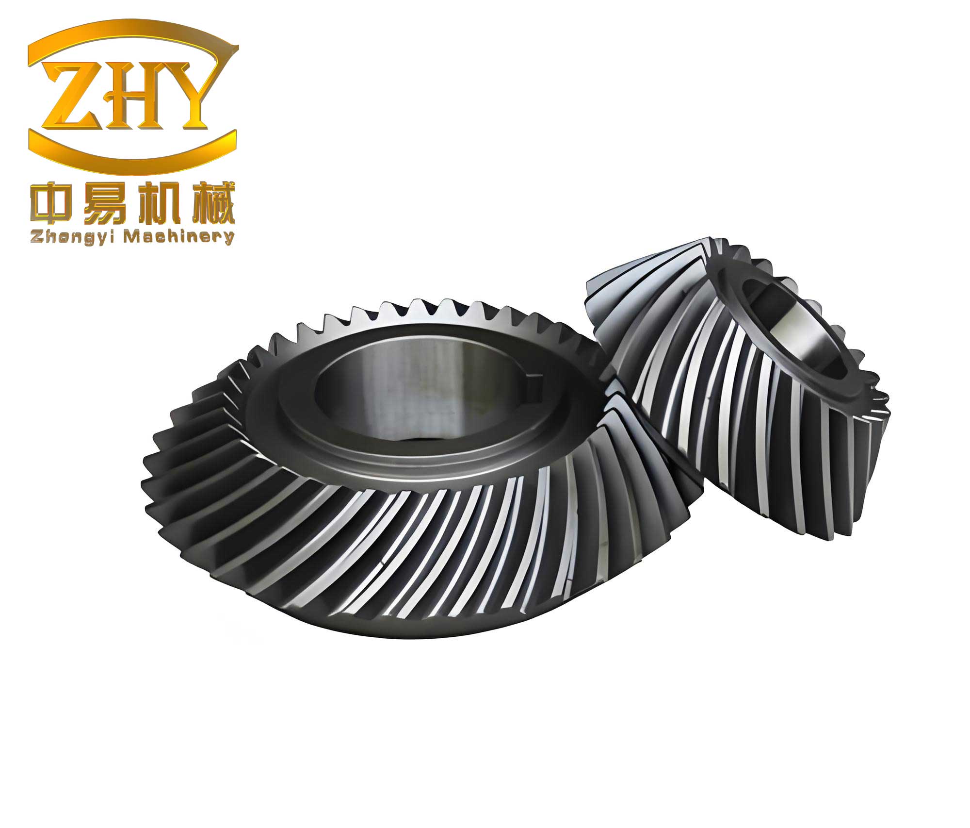
To understand the fluid behavior in spiral gears, I began by establishing a theoretical model for flow leakage. Leakage is a key factor affecting volumetric efficiency, and it occurs primarily through radial and axial gaps. The model incorporates various influences, including original clearances, temperature-dependent viscosity changes, pump body deformation, and flow through sliding bearings. Based on fluid mechanics principles, the continuity and Navier-Stokes equations form the foundation. For incompressible fluid flow, the continuity equation is:
$$ \nabla \cdot \mathbf{u} = 0 $$
And the Navier-Stokes equation is:
$$ \rho \left( \frac{\partial \mathbf{u}}{\partial t} + \mathbf{u} \cdot \nabla \mathbf{u} \right) = -\nabla p + \mu \nabla^2 \mathbf{u} + \mathbf{f} $$
where \( \rho \) is density, \( \mathbf{u} \) is velocity vector, \( p \) is pressure, \( \mu \) is dynamic viscosity, and \( \mathbf{f} \) represents body forces. The radial leakage through the gap between gear tips and pump body is derived by modeling the gap as parallel plates. For a gap height \( \delta \), the velocity profile and flow rate are calculated. The theoretical radial leakage \( Q_1 \) is expressed as:
$$ Q_1 = \left( \frac{\Delta P \delta^3 B}{6 \mu D \cos \beta} – \frac{\pi n R_a \delta B}{30 \cos \beta} \right) $$
where \( \Delta P \) is pressure difference, \( B \) is tooth width, \( D \) is total width of gear tips in transition zone, \( \beta \) is helix angle, \( n \) is rotational speed, and \( R_a \) is tip circle radius. Similarly, axial leakage \( Q_2 \) through the end face gaps is:
$$ Q_2 = \frac{4 (\theta_h + \theta_g) \Delta P \delta_2^3}{3 \mu \ln(R_f / R_n)} $$
where \( \theta_h \) and \( \theta_g \) are angles of high-pressure and transition zones, \( \delta_2 \) is end face gap, \( R_f \) is root circle radius, and \( R_n \) is bearing inner radius. Temperature effects on viscosity are included using the Walther equation:
$$ \log(\log(\nu + a)) = b – c \log T $$
where \( \nu \) is kinematic viscosity, \( T \) is temperature, and \( a, b, c \) are constants. For hydraulic oil, viscosity decreases with temperature, increasing leakage. Pump body deformation under load also enlarges radial gaps, further affecting leakage. Using ANSYS simulations, the deformation is quantified and integrated into the model. Additionally, flow through sliding bearings contributes to overall leakage. The complete leakage model \( Q_{td} \) becomes:
$$ Q_{td} = \left[ \frac{\Delta P (\delta + 0.0326)^2 B}{6 \rho (e^{25.53 – 4.22 \ln T} – 0.6) D \cos \beta} – \frac{\pi n R_a (\delta + 0.0109) B}{30 \rho (e^{25.53 – 4.22 \ln T} – 0.6) \cos \beta} + \frac{4 (\theta_h + \theta_g) \Delta P \delta_2^3}{3 \rho (e^{25.53 – 4.22 \ln T} – 0.6) \ln(R_f / R_n)} + 4 \pi n R B c (1 + \epsilon) \right] \times 60 \times 1000 $$
where \( \epsilon \) is eccentricity, \( c \) is radial clearance, and other parameters are as defined. This comprehensive model allows for predicting leakage under various operating conditions, providing a basis for design improvements in spiral gears.
To analyze dynamic performance, I conducted three-dimensional CFD simulations using Fluent software. The internal flow field of the circular arc helical gear pump was modeled, considering turbulent flow with the Realizable \( k-\epsilon \) model. The governing equations include:
$$ \frac{\partial k}{\partial t} + \frac{\partial (u_i k)}{\partial x_i} = \frac{1}{\rho} \frac{\partial}{\partial x_i} \left[ \left( \mu + \frac{\mu_t}{\sigma_k} \right) \frac{\partial k}{\partial x_i} \right] + G_k + G_b – \rho \epsilon – Y_M $$
$$ \frac{\partial \epsilon}{\partial t} + \frac{\partial (u_i \epsilon)}{\partial x_i} = \frac{1}{\rho} \frac{\partial}{\partial x_i} \left[ \left( \mu + \frac{\mu_t}{\sigma_\epsilon} \right) \frac{\partial \epsilon}{\partial x_i} \right] + \rho C_1 E \epsilon – \rho C_2 \frac{\epsilon^2}{k + \sqrt{\nu \epsilon}} + C_{1\epsilon} \frac{\epsilon}{k} C_{3\epsilon} G_b $$
where \( k \) is turbulent kinetic energy, \( \epsilon \) is dissipation rate, \( \mu_t \) is turbulent viscosity, and other terms are model constants. The geometry was created in SolidWorks and meshed in ANSYS ICEM CFD, with over 1 million tetrahedral cells. Dynamic mesh techniques, including smoothing and remeshing, were applied to handle gear rotation. Boundary conditions set the inlet as pressure-inlet (atmospheric) and outlet as pressure-outlet (load pressure), with gear surfaces as rotating walls.
Simulation results reveal the pressure distribution within spiral gears. Under 25 MPa and 10,000 rpm, pressure decreases gradually from outlet to inlet, with maximum pressure near the meshing zone exceeding the outlet pressure by about 15%. This is lower compared to conventional gear pumps, indicating reduced shock loads. The flow rate fluctuates periodically, and leakage increases with load but decreases with speed. To validate the leakage model, simulated flow rates were compared with theoretical values, showing good agreement. For example, at 25 MPa and 10,000 rpm, the simulated flow was 18.80 L/min, while theoretical was 18.92 L/min. Cavitation effects were also examined using a mixture multiphase model, but found to have minimal impact on pressure and flow fluctuations in high-pressure conditions.
The sliding bearings in spiral gears are critical for supporting radial loads. However, high pressures cause significant radial forces, leading to wear and temperature rise. To address this, bearings with hydrostatic grooves were designed to balance radial forces. I performed CFD simulations on the bearing flow field, analyzing parameters like inlet pressure, speed, eccentricity, inlet position angle, and diameter. The bearing model assumes laminar flow, with Reynolds equation governing pressure distribution:
$$ \frac{\partial}{\partial x} \left( h^3 \frac{\partial p}{\partial x} \right) + \frac{\partial}{\partial z} \left( h^3 \frac{\partial p}{\partial z} \right) = 6 \mu U \frac{\partial h}{\partial x} $$
where \( h \) is oil film thickness, \( U \) is surface velocity. Simulations show that hydrostatic groove pressure is lower than inlet pressure due to pressure drop, balancing only part of the radial force. For instance, at 25 MPa inlet, groove pressure is about 17.9 MPa, balancing 51.9% of radial force. Temperature rise in bearings is significant, with average increases up to 21°C under full load, contributing to overall pump heating. The effects of various parameters are summarized in tables below.
| Parameter | Effect on Hydrostatic Groove Pressure | Effect on Bearing Temperature Rise |
|---|---|---|
| Inlet Pressure Increase | Decreases pressure balance capability | Increases temperature rise |
| Speed Increase | Minimal effect | Increases temperature rise |
| Eccentricity Increase | Slightly decreases pressure balance | Significantly increases temperature rise |
| Inlet Position Angle (optimal 47°) | Slight decrease with angle | Minimized at 47° |
| Inlet Diameter (optimal 2.4 mm) | Increases pressure balance | Decreases temperature rise |
Based on these findings, I proposed design improvements for spiral gears bearings: optimizing inlet position angle to 47° and diameter to 2.4 mm. This enhances pressure balance and reduces thermal effects, as confirmed by subsequent experiments.
To verify theoretical and simulation results, I built an experimental test platform for the circular arc helical gear pump. The system includes temperature sensors (KZW/P-201S), flow sensor (LWGB-15), pressure sensor (HSTL800A1B3C1D1E2F1), and torque-speed sensor (JN338-100AG), with data acquisition via PCI-1710 card and LabVIEW software. Tests were conducted under varying loads and speeds, measuring temperature rise and flow rate.
Temperature tests show that optimized bearings reduce surface temperature rise by about 3.1°C at 2100 rpm and 8 MPa, compared to unoptimized bearings. Load and speed increases generally elevate temperature, but at low loads, the effect is less pronounced due to changes in eccentricity and flow. Flow tests demonstrate that leakage decreases with speed and increases with load, aligning with model predictions. The volumetric efficiency improves with optimized bearings, reaching 64.43% at 7500 rpm and 8 MPa. Comparison between theoretical and experimental flow rates validates the leakage model, though discrepancies exist at high speeds due to wear and thermal expansion.
In conclusion, this research provides a comprehensive analysis of dynamic performance in circular arc helical gear pumps. The developed leakage model, incorporating multiple factors, accurately predicts flow losses. CFD simulations reveal that spiral gears operate with lower pressure fluctuations than conventional designs, suitable for high-pressure high-speed applications. Bearing optimization through parameter adjustment enhances radial force balance and reduces temperature rise. Experimental results confirm the effectiveness of these improvements. Future work may focus on advanced sealing materials and further refinement of leakage models for extreme conditions. This study contributes to the advancement of spiral gears technology in hydraulic systems, ensuring reliability and efficiency in demanding environments.