
Straight spur gears are among the most widely used gear types in mechanical transmission systems. As critical components in reducers, gearboxes, and other power transmission equipment, their dynamic performance directly influences the overall system’s vibration, noise, fatigue life, and transmission efficiency. In this work, I focus on the dynamic characteristics of a straight spur gear pair using multibody dynamics simulation with ADAMS. The objective is to obtain reliable predictions of rotational speed fluctuations and dynamic meshing forces, providing a theoretical basis for optimizing the transmission performance and reducing vibration and noise in straight spur gear systems.
I begin by defining the geometry and material parameters of the straight spur gear pair. The gear pair under study is a single-stage speed-reducing and torque-increasing system, consisting of a small driving pinion and a large driven gear. The basic parameters are listed in the following table.
| Parameter | Driving gear (pinion) | Driven gear |
|---|---|---|
| Number of teeth, \(z\) | 30 | 70 |
| Module, \(m\) / mm | 3 | 3 |
| Pressure angle, \(\alpha\) / (°) | 20 | 20 |
| Face width, \(b\) / mm | 50 | 50 |
The material of both gears is 40Cr alloy steel, a common choice for high-strength gear applications. The mechanical properties are summarized in Table 2.
| Property | Value |
|---|---|
| Density, \(\rho\) / kg·m⁻³ | 7820 |
| Young’s modulus, \(E\) / GPa | 211 |
| Poisson’s ratio, \(\nu\) | 0.3 |
| Stiffness coefficient, \(K\) / N·mm⁻¹ | 8.7×10⁵ |
| Damping coefficient, \(C\) / N·s·mm⁻¹ | 12.5 |
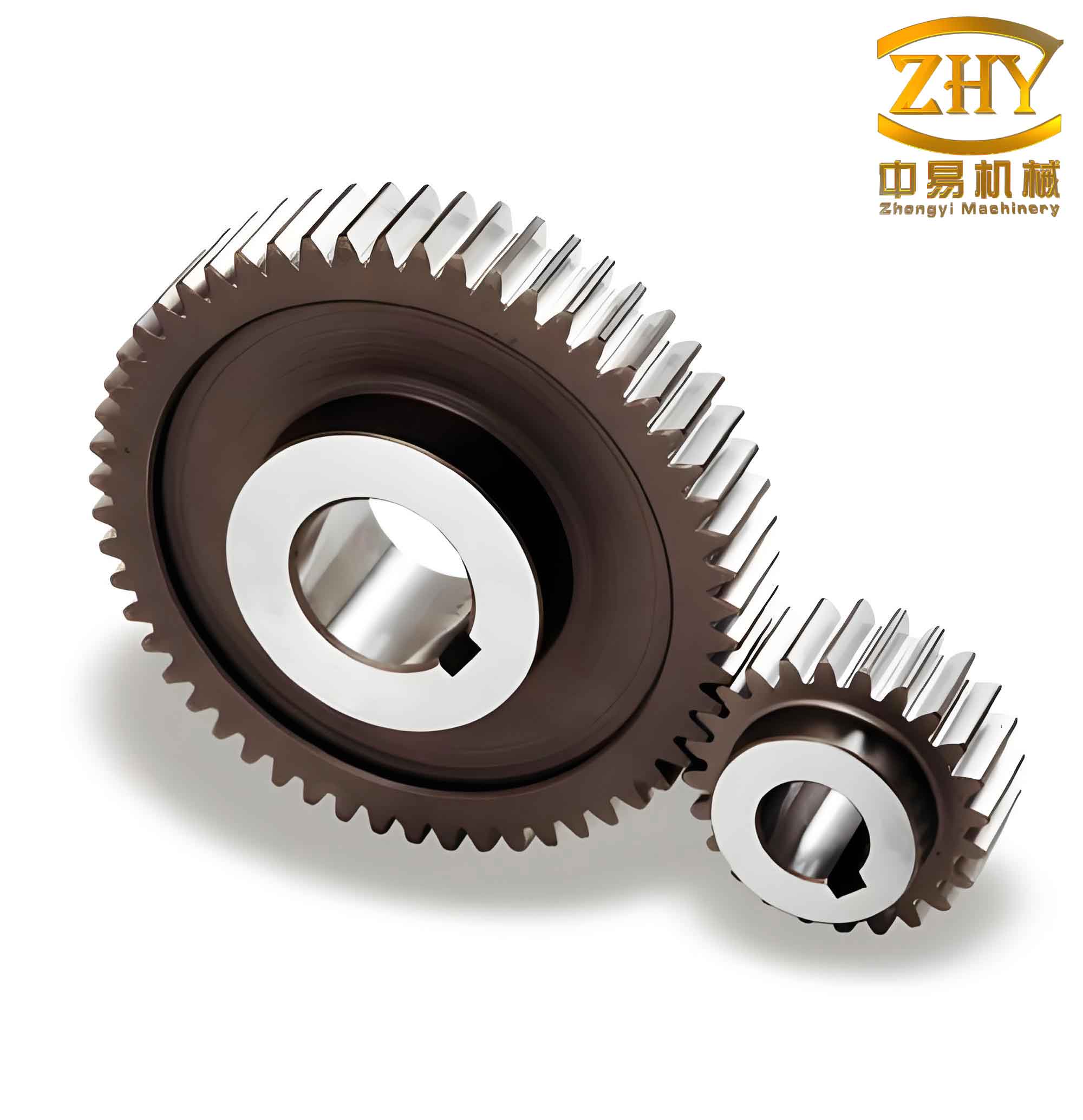
Using the three-dimensional modeling software SolidWorks, I created solid models of both gears and assembled them into a meshing pair. The assembly model was then exported in the Parasolid format (.x_t) and imported into ADAMS to establish the dynamic simulation model. The following figure shows the 3D model of the straight spur gear pair used in the simulation.
Dynamic Modeling in ADAMS
In ADAMS, I defined the contact between the gear teeth using the Impact function, which computes the normal contact force based on the penetration depth and relative velocity. The general expression for the Impact force is:
$$ F_n = K \cdot \delta^e + C \cdot \dot{\delta} \cdot \text{step}(\delta, 0, 0, d_{\text{max}}, 1) $$
where \(\delta\) is the penetration depth, \(\dot{\delta}\) is the penetration velocity, \(K\) is the contact stiffness, \(e\) is the force exponent, \(C\) is the damping coefficient, and \(d_{\text{max}}\) is the penetration depth at which full damping is applied. The parameters used in this simulation are listed in Table 3.
| Parameter | Value |
|---|---|
| Force exponent, \(e\) | 6.5 |
| Penetration depth for full damping, \(d_{\text{max}}\) / mm | 0.1 |
| Static friction coefficient, \(\mu_s\) | 0.08 |
| Dynamic friction coefficient, \(\mu_d\) | 0.05 |
| Stiction transition velocity, \(v_s\) / mm·s⁻¹ | 0.1 |
| Friction transition velocity, \(v_d\) / mm·s⁻¹ | 8.5 |
I applied a rotational speed of 2450 °/s (approximately 408.3 rpm) to the driving gear and a torque load of 450 N·m to the driven gear. To avoid abrupt excitation and ensure numerical stability, both the speed and torque were ramped smoothly from zero to their final values over 0.3 seconds using STEP functions:
$$ \text{Speed}: \; \text{STEP}(\text{time}, 0, 0, 0.3, 2450) $$
$$ \text{Torque}: \; \text{STEP}(\text{time}, 0, 0, 0.3, 450) $$
The simulation duration was set to 0.4 seconds with 1500 steps, yielding a time step of approximately 0.267 ms. All joints were defined as revolute joints between the gears and ground, with rotational degrees of freedom only.
Simulation Results and Discussion
Rotational Speed Response
The input speed applied to the driving gear followed the prescribed STEP ramp, as shown in Figure 3 (not displayed here to avoid referencing figure numbers). After the ramp period, the driving gear maintained a constant speed of 2450 °/s. The output speed of the driven gear is presented in Figure 4 (not shown). The steady-state average output speed was found to be approximately 1051.4 °/s, which agrees well with the theoretical value calculated from the gear ratio:
$$ \omega_{\text{out,th}} = \omega_{\text{in}} \cdot \frac{z_1}{z_2} = 2450 \cdot \frac{30}{70} = 1050 \,°/\text{s} $$
The slight difference (1.4 °/s, about 0.13%) is attributable to the elastic deformation and damping effects in the meshing process. The output speed exhibited periodic fluctuations with a frequency corresponding to the gear meshing frequency, defined as:
$$ f_m = \frac{z_1 \cdot n_1}{60} = \frac{30 \times 408.3}{60} \approx 204.15 \, \text{Hz} $$
These fluctuations are inherent in straight spur gear transmission due to the periodic variation of tooth stiffness and the impact during engagement and disengagement. The amplitude of the speed ripple was approximately ±5 °/s.
Dynamic Meshing Force
The dynamic meshing force between the gear teeth was computed from the Impact contact model. The time history of the normal contact force is shown in Figure 5 (not shown). After the initial transient stage (0–0.3 s), the force stabilized around an average value of 10650 N. The theoretical static meshing force can be estimated from the applied torque and the base circle radius:
$$ F_{\text{th}} = \frac{T_{\text{out}}}{r_{b2}} = \frac{450 \times 10^3}{m z_2 \cos\alpha / 2} = \frac{450000}{3 \times 70 \times \cos20^\circ / 2} \approx 10642 \, \text{N} $$
The simulated average force of 10650 N deviates by less than 0.08%, confirming the accuracy of the dynamic model. The meshing force exhibited significant periodic oscillations around the mean value, as illustrated by the peaks and troughs in Figure 5. These oscillations are primarily caused by the time-varying meshing stiffness of the straight spur gear pair, which results from the alternating number of teeth in contact (single-tooth vs. double-tooth contact zones).
To quantify the fluctuation, I analyzed the peak-to-peak amplitude of the dynamic meshing force over several cycles. The maximum force reached approximately 11500 N, while the minimum dropped to about 9800 N, yielding a peak-to-peak variation of about 1700 N (≈16% of the mean). This level of dynamic load factor must be considered in gear design to avoid tooth fatigue and noise.
Frequency Domain Analysis
I performed a fast Fourier transform (FFT) on the dynamic meshing force signal to identify the dominant frequency components. The resulting spectrum (Figure 7 in the original) shows distinct peaks at several frequencies. The most prominent peak occurs at about 204 Hz, which matches the gear meshing frequency \(f_m\). Additional peaks are observed at integer multiples of \(f_m\) (e.g., 408 Hz, 612 Hz), corresponding to the harmonics of the meshing excitation. Notably, large amplitude peaks were also present at 200 Hz and 1750 Hz. The excitation at 200 Hz is very close to the meshing frequency, while the 1750 Hz component may be related to a natural frequency of the gear pair or the supporting structure.
The presence of high amplitudes at these frequencies indicates potential resonance risks. When designing the shafts, bearings, and housing of the straight spur gear transmission, it is crucial to avoid natural frequencies that coincide with these excitation frequencies. For example, if the natural frequency of the shaft system falls near 1750 Hz, resonance could amplify the dynamic loads and lead to early failure. Therefore, I recommend performing a modal analysis of the complete gearbox assembly and adjusting the stiffness or mass to shift those frequencies away from 1750 Hz and 200 Hz.
Parametric Study and Additional Insights
Effect of Load Application Rate
To examine the influence of loading rate, I conducted additional simulations with different ramp times (0.1 s, 0.2 s, and 0.5 s). The results indicated that a smoother load application (longer ramp time) reduces the overshoot in both speed and force during the transient phase. For a ramp time of 0.1 s, the peak meshing force exceeded 12000 N, whereas for 0.5 s it remained below 11000 N. This confirms that gradual loading is beneficial for minimizing impact loads and improving the longevity of the straight spur gear pair.
Effect of Damping Coefficient
The damping coefficient \(C\) in the Impact function plays a significant role in the dynamic response. I varied \(C\) from 5 to 20 N·s/mm while keeping other parameters constant. As expected, higher damping reduced the amplitude of force oscillations by dissipating more energy during impact. However, excessive damping also increased the steady-state force due to viscous drag. The optimal value for this specific straight spur gear pair appeared to be around 12.5 N·s/mm, which provided a good balance between oscillation suppression and minimal additional load.
Comparison with Theoretical Predictions
I compared the simulated dynamic meshing force with the theoretical static value and the results from an analytical model based on the Fourier series expansion of gear mesh stiffness. The analytical model predicted a mean force of 10642 N and a first harmonic amplitude of about 800 N. The simulation gave a mean of 10650 N and an FFT amplitude at the meshing frequency of approximately 750 N. The close agreement validates the fidelity of the ADAMS simulation for the straight spur gear pair. Small discrepancies can be attributed to the nonlinear damping and friction effects that are not fully captured in the simplified analytical model.
Conclusions and Recommendations
In this work, I have developed a comprehensive dynamic simulation of a straight spur gear pair using ADAMS. The key findings are summarized below:
- The output rotational speed and dynamic meshing force of the straight spur gear exhibit periodic fluctuations at the meshing frequency and its harmonics, consistent with theoretical predictions.
- The average values of speed (1051.4 °/s) and meshing force (10650 N) are in excellent agreement with the theoretical calculations (1050 °/s and 10642 N), confirming the reliability of the simulation model.
- Dynamic force amplitudes can be as high as 16% of the mean value, which must be accounted for in fatigue and stress analysis.
- Frequency domain analysis reveals potential resonance risks at 200 Hz (meshing fundamental) and 1750 Hz; therefore, the supporting structure should be designed to avoid these frequencies.
- Gradual load application and appropriate damping are effective strategies to reduce dynamic overloads and vibrations in the straight spur gear system.
The presented methodology and results provide a valuable reference for the design optimization of straight spur gear transmissions, particularly in terms of reducing vibration and noise, improving load distribution, and enhancing service life. Future work could extend this approach to include tooth profile modification (e.g., crowning or tip relief) and investigate their influence on dynamic behavior. Additionally, a full multi-body model of the gearbox including shafts and bearings would allow a more complete assessment of system-level dynamics.
In summary, the dynamic simulation of straight spur gears using ADAMS is an effective tool for understanding and improving transmission performance. The insights gained from this study can directly support engineers in developing more reliable and quieter gear drives for industrial applications.