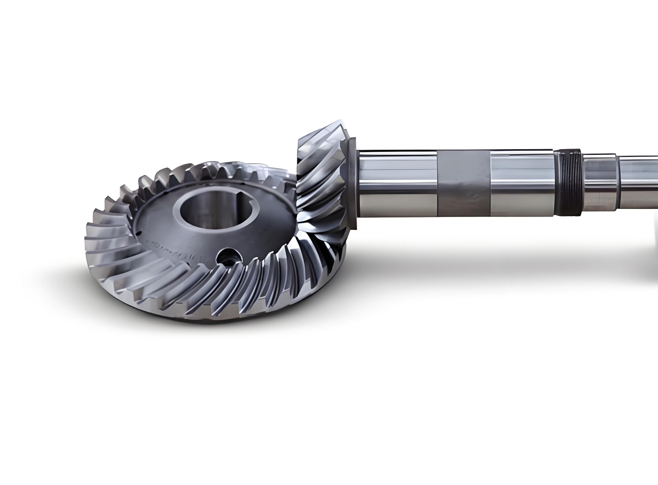
This study proposes a method to analyze the dynamic transmission error (DTE) of spiral bevel gears by incorporating actual tooth surfaces, material damping, rotational speed, and elastic support systems. The research combines geometric properties, finite element analysis (FEA), and dynamic modeling to evaluate the effects of tooth surface errors, operating conditions, and system flexibility on gear performance.
Mathematical Modeling
The dynamic transmission error for spiral bevel gears is defined as the deviation between the actual and theoretical angular positions of the driven gear. The governing equation for the gear system dynamics is expressed as:
$$ \mathbf{M}\{\ddot{q}\} + \mathbf{C}\{\dot{q}\} + \mathbf{K}\{q\} = \{F\} $$
where \( \mathbf{M} \), \( \mathbf{C} \), and \( \mathbf{K} \) represent the mass, damping, and stiffness matrices, respectively. \( \{q\} \) denotes the generalized displacement vector, and \( \{F\} \) is the external load vector.
The relative displacement along the meshing direction, considering tooth surface errors and elastic support, is formulated as:
$$ x_n = \sum_{i=1,2} \left[ (x_i + r_{pi}\theta_{iy}) \cos\delta_i \sin\alpha_n \pm (y_i \pm r_{pi}\theta_{ix}) \Gamma_i \right] – e_n(t) $$
where \( \Gamma_i = \cos\delta_i\cos\alpha_n\sin\beta_i \pm \sin\delta_i\sin\alpha_n \), \( e_n(t) \) is the static transmission error, and \( r_{pi} \), \( \delta_i \), \( \beta_i \), and \( \alpha_n \) denote pitch radii, pitch angles, spiral angles, and pressure angle, respectively.
Gear Parameters and Tooth Surface Error

The geometric parameters of the spiral bevel gears are summarized below:
| Parameter | Pinion | Gear |
|---|---|---|
| Module | 4.65 | 4.65 |
| Teeth | 11 | 43 |
| Spiral Angle (°) | 35 | 35 |
| Pitch Diameter (mm) | 51.15 | 199.95 |
| Pressure Angle (°) | 20 | 20 |
Tooth surface errors were measured using coordinate metrology and mapped onto finite element models. The maximum observed error amplitude reached 12 μm, significantly impacting dynamic behavior.
Finite Element Analysis
The ABAQUS-based FEA model incorporated:
$$ \text{Material: Alloy Steel (E = 209 \, \text{GPa}, \nu = 0.3) $$
$$ \text{Element Type: C3D8R (8-node linear hexahedron)} $$
$$ \text{Contact: Penalty method (friction coefficient = 0.1)} $$
$$ \text{Damping: Rayleigh model (α = 0.03, β = 3 \times 10^{-6})} $$
Three configurations were analyzed:
- Theoretical tooth surfaces
- Actual gear surface + theoretical pinion
- Actual tooth surfaces for both gears
Dynamic Transmission Error Characteristics
The DTE under varying loads (50–350 N·m) and speeds (20–40 rad/s) revealed:
| Condition | DTE Amplitude (μrad) | Fluctuation Period (ms) |
|---|---|---|
| Theoretical Surfaces | 18–42 | 5.2 |
| Actual Gear Surface | 25–58 | 4.8 |
| Both Actual Surfaces | 34–72 | 4.1 |
The DTE evolution follows:
$$ \delta(t) = \Delta\theta_2 – \frac{z_1}{z_2}\Delta\theta_1 + \sum_{k=1}^n A_k e^{-\zeta\omega_n t}\sin(\omega_d t + \phi_k) $$
where \( \omega_d = \omega_n\sqrt{1-\zeta^2} \) represents the damped natural frequency, and \( A_k \) denotes error-induced excitation amplitudes.
Speed and Support System Effects
Increasing rotational speed amplified initial DTE fluctuations:
$$ \text{Peak DTE at 20 rad/s: } 58 \, \mu\text{rad} $$
$$ \text{Peak DTE at 40 rad/s: } 83 \, \mu\text{rad} $$
Elastic support systems introduced additional compliance:
| Support Type | Resonance Frequency (Hz) | DTE Increase (%) |
|---|---|---|
| Rigid | 1,250 | – |
| Elastic | 980 | 27–41 |
Conclusion
This study demonstrates that actual tooth surface errors increase spiral bevel gear DTE amplitudes by 38–62% compared to theoretical surfaces. Speed-dependent effects and elastic support interactions further amplify dynamic responses. The proposed methodology enables comprehensive evaluation of spiral bevel gear dynamics for vibration and noise control in automotive transmissions.
Critical findings include:
- Tooth surface errors dominantly affect high-frequency DTE components (>800 Hz)
- Elastic supports reduce system stiffness by 22%, increasing low-frequency fluctuations
- Nonlinear DTE-speed relationships require multi-parameter optimization for NVH control
Future work will investigate microgeometry modifications to compensate for error-induced DTE in spiral bevel gear systems.
