
The cylindrical gear transmission system is widely used in industry, and the meshing and dynamic characteristics of cylindrical gear transmission are related to the smoothness and reliability of the entire equipment. The large number of manufacturing and installation errors in engineering can cause changes in the contact state of cylindrical gear teeth, thereby affecting the development of cylindrical gear tooth surface damage (such as peeling, wear, and bonding), and further affecting the dynamic behavior of cylindrical gear systems. Numerous studies have focused on the impact of manufacturing errors or tooth surface damage on the meshing and response characteristics of cylindrical gears.
Accumulated pitch error is a common manufacturing error in cylindrical gears, and many scholars at home and abroad have analyzed the impact of pitch error on the dynamic characteristics of the system. Wang Qibin et al. studied the effect of tooth pitch deviation on the dynamic characteristics of spur gear rotor systems, and the results showed that tooth pitch deviation can cause sideband frequencies to appear near the meshing frequency. Based on the contact analysis method of gear teeth, Yuan et al. established a dynamic model of helical gears considering the cumulative error of tooth pitch, and extended it to herringbone gears.
During the operation of cylindrical gears, wear on the tooth surface is inevitable. The research on wear can mainly be divided into quasi-static assumptions and dynamic assumptions. Based on the Archard wear model, Zhang Jun et al. established a wear prediction model for spur gear pairs under quasi-static conditions and studied the effect of misalignment and torque on wear. Ding et al. coupled the dynamic model of cylindrical gears with the Archard wear model to establish a dynamic wear prediction model, revealing the interaction between wear and dynamic behavior. Feng et al. established an improved dynamic wear prediction model for cylindrical gear pairs and verified the effectiveness of the wear prediction model through experiments.
From the above literature, it can be seen that existing wear models ignore the non-uniformity of inter tooth wear and assume that the wear amount on each gear tooth is the same. However, for actual cylindrical gear pairs, the presence of accumulated tooth pitch errors can alter the distribution of load between teeth, leading to uneven wear between teeth. Due to the lack of corresponding theoretical and model support, there is currently no literature that combines dynamic models considering tooth pitch errors with wear models to quantitatively analyze the impact of tooth pitch errors on wear uniformity. In response to the above issues, this article proposes a dynamic wear prediction model for cylindrical gear pairs that considers tooth pitch error, and analyzes the inherent law between the number of teeth of the driving/driven gears and the distribution of wear.
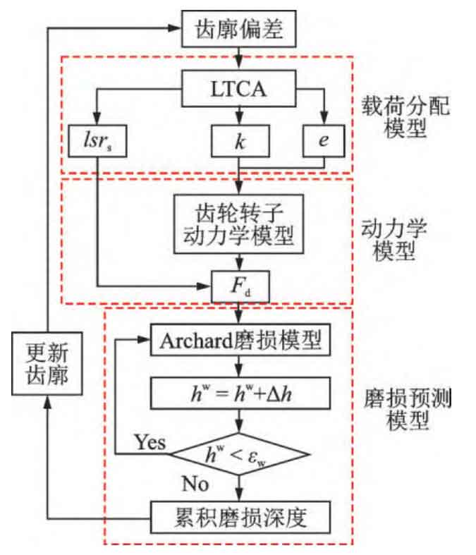
1. Dynamic wear model considering tooth pitch error
1.1 Load distribution algorithm considering cumulative tooth pitch error
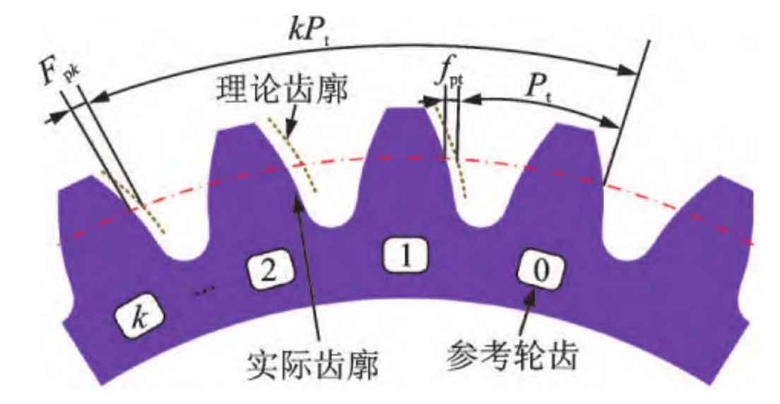
Due to machining errors, the actual tooth profile often deviates from the theoretical involute tooth profile, causing meshing teeth to participate in meshing earlier or later. The schematic diagram of accumulated tooth pitch error is shown in Figure 1. Pt is the theoretical tooth pitch, fpt is the tooth pitch error, and Fpk is the accumulated tooth pitch error corresponding to the k-th gear tooth. A tooth pitch error greater than zero indicates that the actual tooth thickness is greater than the theoretical tooth thickness, while conversely, it indicates that the actual tooth thickness is less than the theoretical tooth thickness.
The tooth load contact analysis (LTCA) method takes into account both accuracy and solving efficiency, and can effectively consider various forms of tooth profile errors. Therefore, this paper adopts the LTCA method to obtain the load distribution of cylindrical gear pairs with tooth profile deviations. The core idea of the LTCA method is to separate the overall deformation and contact deformation during the meshing process of cylindrical gears. The contact deformation is calculated using analytical formulas to improve calculation efficiency, and the overall deformation is calculated using the finite element method.
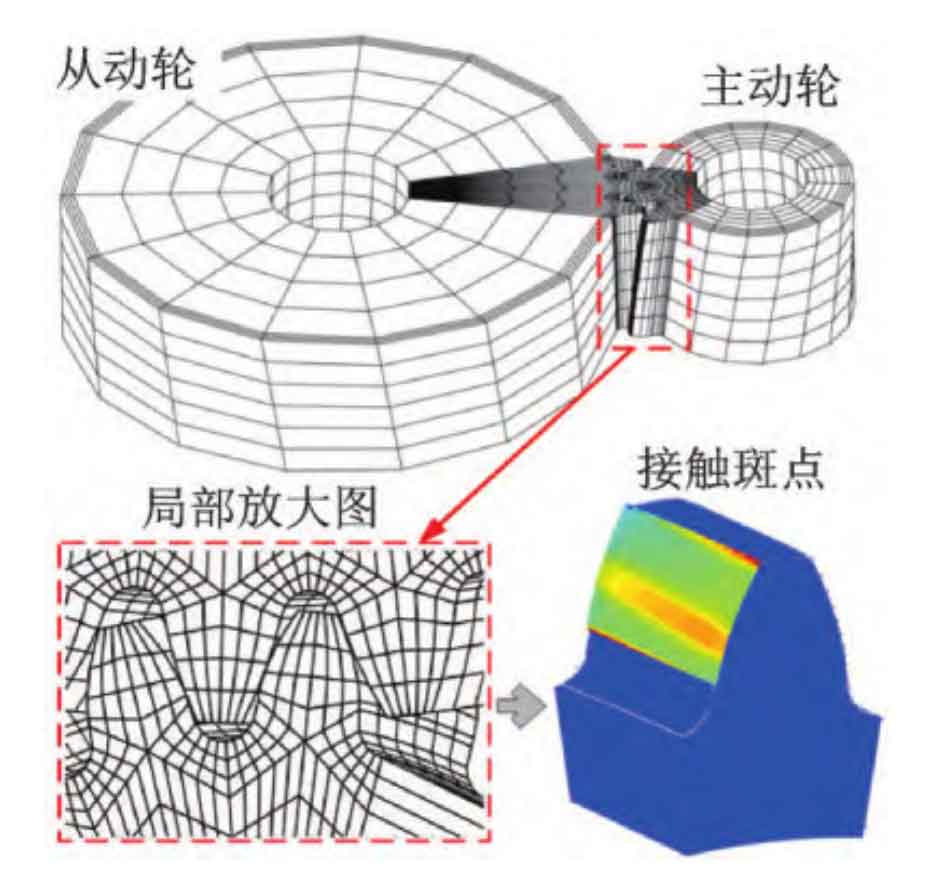
In order to improve the universality and computational efficiency of the program, the finite element calculation process in this article is implemented in the MATLAB environment. The finite element mesh constructed in MATLAB is shown in Figure 2.
The LTCA method calculates the normal displacement of the tooth surface, so it is necessary to convert the accumulated error of tooth pitch into the normal displacement of the tooth surface:
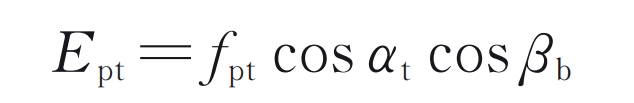
In the formula α T is the end face pressure angle; β B is the helix angle of the base circle.
The overall flexibility matrix can be expressed as:
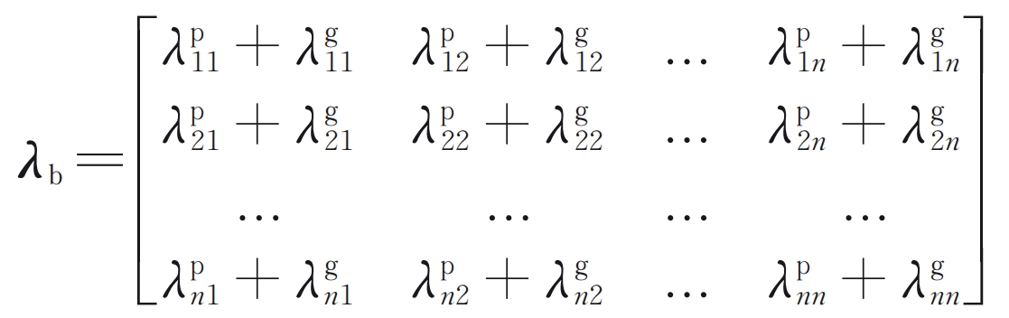
In the formula, the subscripts i and j respectively represent applying a unit force at point j and extracting displacement at point i; The superscripts p and g represent the driving wheel and the driven wheel, respectively; N represents the number of potential touchpoints.
The local contact flexibility matrix is:
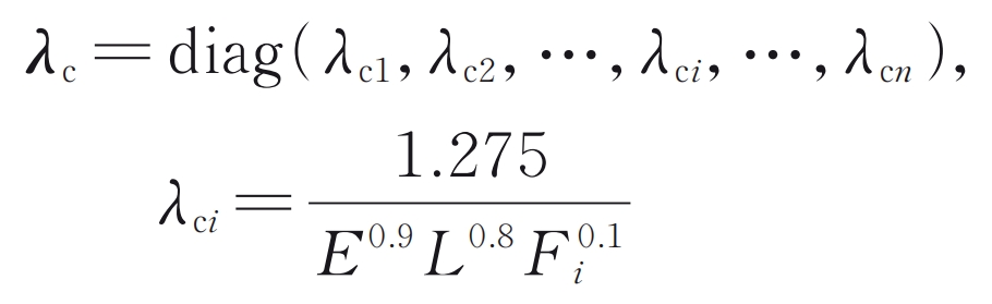
In the formula: Fi is the contact force of the i-th potential contact point; E and L are the elastic modulus and tooth width, respectively.
The iterative equation for the contact analysis of gear teeth is:

In the formula: Fn is the normal contact force vector, which is the load distribution information on the tooth surface; δ S is the static transmission error; Fs=T/rb1, representing static meshing force, where T and rb1 are the input torque and the radius of the driving wheel base circle, respectively; ε The tooth profile deviation vector should include the tooth separation distance, tooth modification amount, and accumulated tooth pitch error. I is a vector with all elements equal to 1, and the subscript represents the dimension of the vector.
Solve the nonlinear equation shown in equation (4) to obtain the tooth surface load distribution force Fn and static transmission error δ S. The expression for the meshing stiffness of cylindrical gear pairs is:
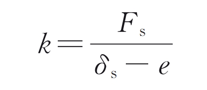
In the formula, e represents the no-load transmission error.
1.2 Dynamic model of cylindrical gear rotor system considering tooth pitch error
The meshing relationship between the input shaft and output shaft is simulated through a meshing unit, as shown in Figure 3. Considering bending, torsion, and axial degrees of freedom, establish a cylindrical gear meshing element, whose generalized coordinates are:

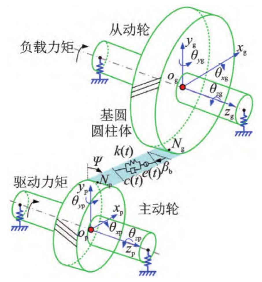
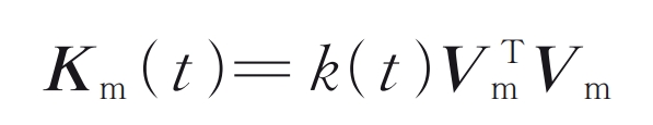
Use the projection vector Vm to project the displacement of the cylindrical gear in the direction of the meshing line:
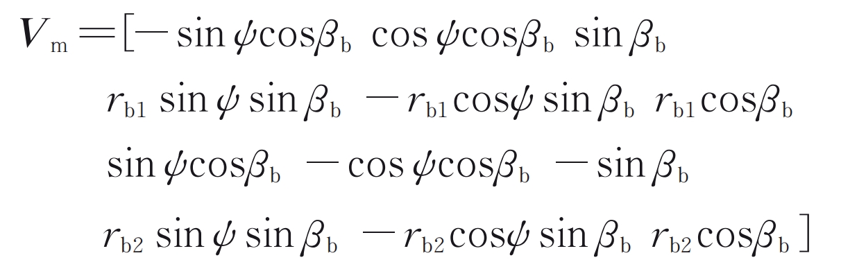
In the formula ψ Indicates the angle between the meshing plane and the y-axis (as shown in Figure 3); RB2 represents the radius of the base circle of the driven wheel. The stiffness matrix of the cylindrical gear meshing unit is:
The Timoshenko beam element is used to simulate the flexibility of the shaft, and linear springs are used to simulate the bearing support at both ends of the transmission shaft. Assemble meshing elements, beam elements, and bearing elements to form an overall stiffness matrix. The overall dynamic equation of the cylindrical gear rotor system is:

In the formula, M, C, G, and K respectively represent the mass matrix, damping matrix, gyroscopic matrix, and stiffness matrix; F is the external load vector; X is the displacement array. The damping in this model adopts a proportional damping form.
The dynamic meshing force can be expressed as:
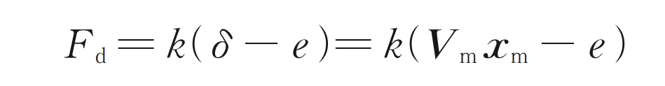
In the formula: δ To dynamically transmit errors.
For traditional cylindrical gear rotor dynamics analysis, the variation period of vibration response is generally the meshing period. However, due to the accumulation of tooth pitch errors, a chasing tooth cycle should be taken for dynamic analysis:
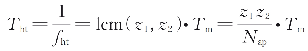
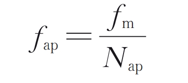
In the formula: Tm is the meshing period of the cylindrical gear; The LCM function represents taking the least common multiple of two numbers; Nap is the combined state coefficient, whose value is the maximum common divisor of the number of teeth of two cylindrical gears; Z 1 and z 2 are the number of teeth of the driving wheel and the driven wheel, respectively; FHT is the frequency of chasing teeth, which represents the frequency at which two specific teeth on the driving and driven wheels meet once:
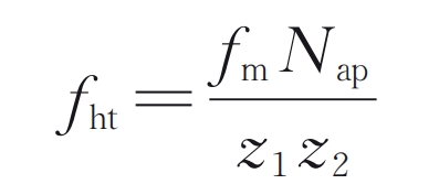
In the formula, fm is the meshing frequency. According to the definition of chasing tooth frequency, when the minimum common multiple of the number of teeth of two cylindrical gears is small, and even when the number of teeth of cylindrical gears is prime, the chasing tooth frequency is very low. In addition, the non-uniformity of meshing between teeth can also lead to the frequency of combined states:
1.3 Wear prediction model based on Archard wear theory
Using the Archard wear model to calculate the wear depth caused by a single wear is:
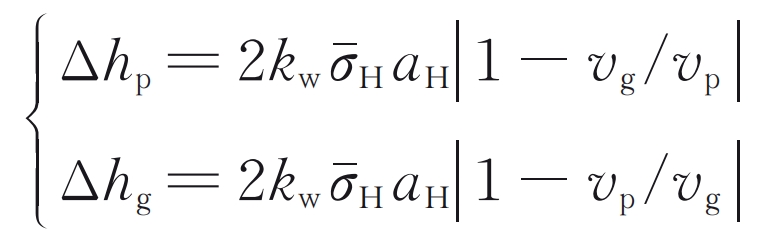
In the formula, vp and vg are the slip velocities at the meshing points of the driving wheel and the driven wheel, respectively; AH is the half width of the Hertz contact area:
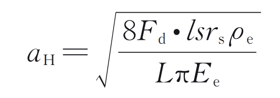
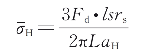
In the formula, lsrs is the static load distribution coefficient obtained by the LTCA method; ρ E and Ee are the equivalent curvature radius and equivalent elastic modulus of cylindrical gear pairs, respectively.
σˉ H is the average stress in the Hertz contact area:
Kw is the wear coefficient considering different lubrication states:
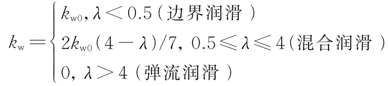
In the formula λ For film thickness ratio:
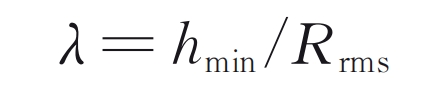
In the formula, Rrms represents the comprehensive surface roughness of cylindrical gears; Hmin is the minimum oil film thickness:
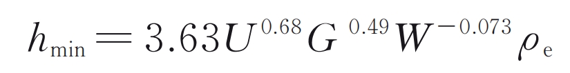
In the formula, W, G, and U represent non dimensional load parameters, material parameters, and velocity parameters, respectively.
Kw0 is the wear coefficient under boundary lubrication state:
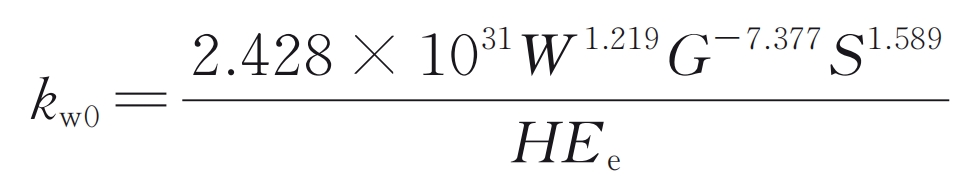
In the formula: S is a dimensionless roughness parameter; H is the Rockwell hardness of the tooth surface. In order to consider the coupling relationship between dynamics and wear, it is necessary to use an iterative approach for dynamic wear simulation. In order to improve computational efficiency, there is no need to allocate loads and solve dynamic models for each wear cycle. Instead, when the accumulated wear depth is greater than the wear update threshold ε W (take 2) μ m) The tooth profile will only be updated later. By using this method, the entire life cycle wear process can be divided into several stages, within which the load distribution and steady-state vibration response are considered constant. The specific iteration process is shown in Figure 4.
2. Model validation
The experimental results of dynamic transmission error of cylindrical gear pairs with accumulated tooth pitch error in literature were used to verify the effectiveness of the model proposed in this paper. For the convenience of comparing with the experimental results in the literature, the tooth profile deviation parameters consistent with the experiments in the literature are adopted, and the forms of tooth profile deviation included include: tooth profile modification, tooth direction modification, cumulative tooth pitch error, and geometric eccentricity. The gear pair parameters, tooth profile deviation parameters, shaft section parameters, and bearing stiffness parameters are detailed in the literature.
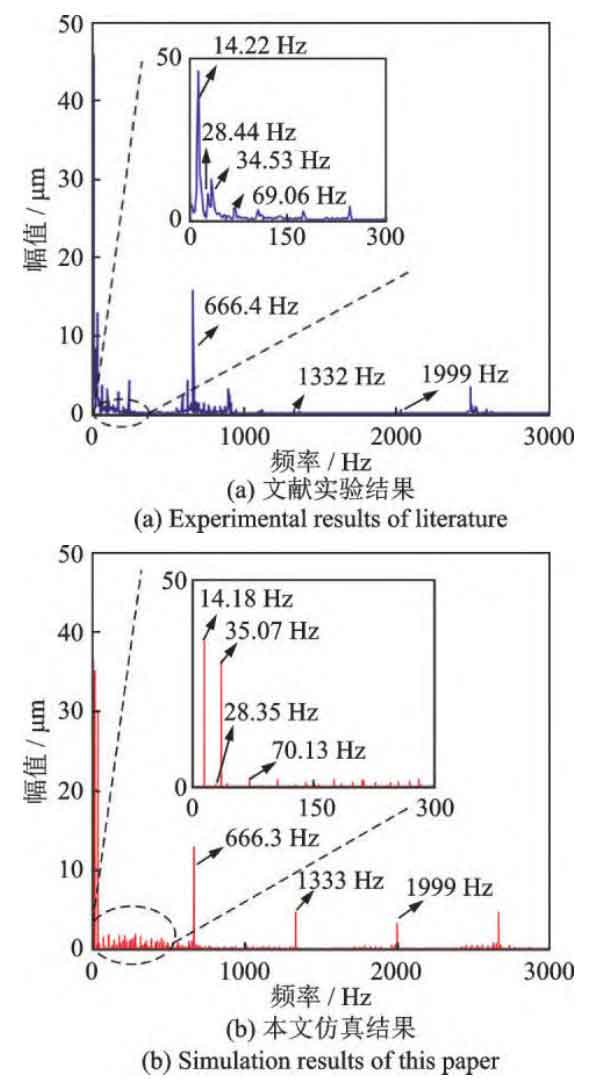
The comparison of the dynamic transmission error spectra between the model and the measured data in this article is shown in Figure 5. From Figure 5, it can be seen that the rotational frequency component caused by the accumulated error of tooth pitch is very obvious, showing a very obvious sideband near the meshing frequency. The spectral characteristics of the model in this article are very similar to those obtained from experiments in the literature, indicating the effectiveness of the simulation model in this article.
3. Result analysis and discussion
3.1 Analysis of meshing characteristics
Perform dynamic wear simulation using the parameters shown in Table 1. The diameters of the driving shaft and the driven shaft are 60 mm and 100 mm, respectively. The length of the shaft is 300 mm. The bearing stiffness is shown in Table 2, ignoring the bearing damping.
| Parameter | Driving wheel/driven wheel | Parameter | Driving wheel/driven wheel |
| Number of teeth | 28/56 | Tooth width/mm | 40 |
| Elastic modulus/GPa | 210 | Pressure angle/(°) | 20 |
| Poisson’s ratio | 0.3 | Torque/(N ⋅ m) | 500 |
| Inner hole radius/mm | 30/50 | Speed/(r ⋅ min ^ -1) | 2865 |
| Normal modulus/mm | 4 | Tooth top height coefficient | 1 |
| Spiral angle/(°) | 0 | Displacement coefficient | 0 |
| Parameter | Numerical value |
| kxx /(N⋅m-1) | 1.7×10^8 |
| kyy /(N⋅m-1) | 1.7×10^8 |
| kzz /(N⋅m-1) | 7.6×10^7 |
| kθxθx /(N⋅m⋅rad-1) | 1×10^6 |
| kθyθy /(N⋅m⋅rad-1) | 1×10^6 |
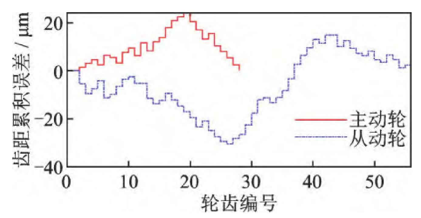
The cumulative error of tooth pitch between the driving wheel and the driven wheel is based on the measured results in the literature, as shown in Figure 6.
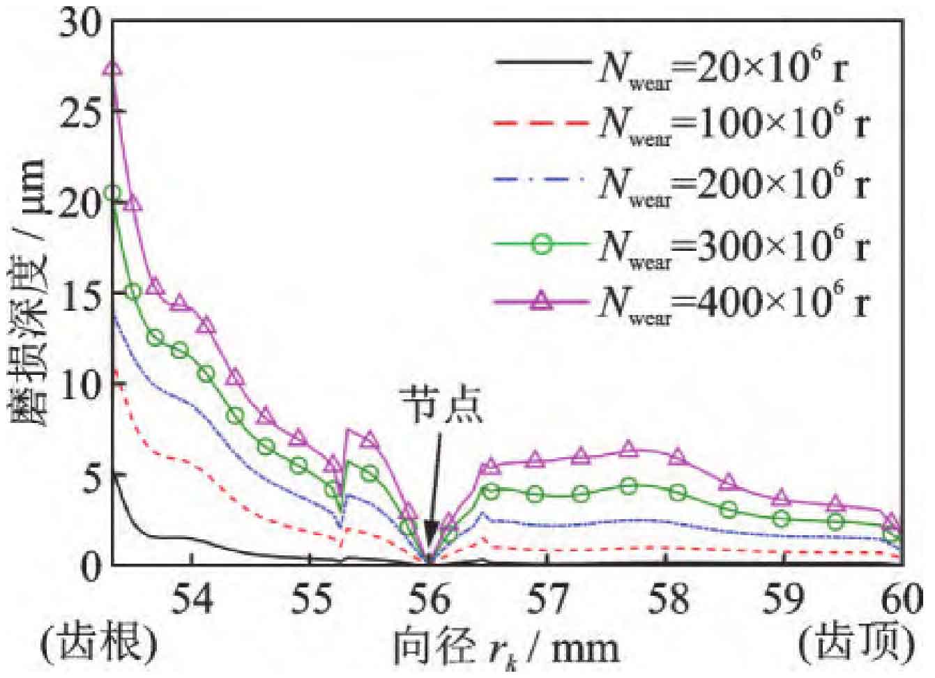
As shown in Figure 7, the accumulated wear depth of the middle surface of the active gear tooth width under different operating times is shown. The node position has zero wear due to its zero relative slip velocity. There is significant wear at the root and top of the teeth. As the number of runs increases, due to severe wear at the root and top of the teeth, the contact stress in this area decreases and the wear rate slows down.
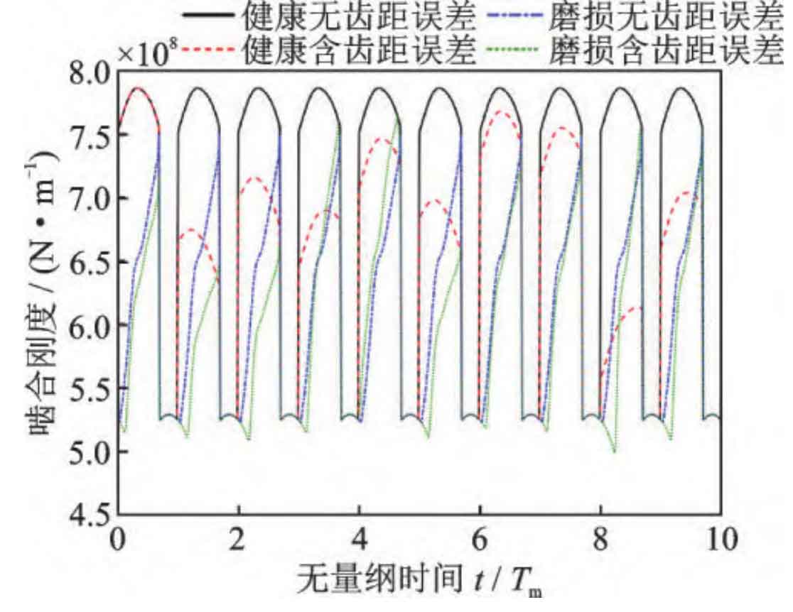
The time-varying mesh stiffness under different conditions is shown in Figure 8. For gear pairs without accumulated pitch error, the meshing stiffness within each meshing cycle is the same. The introduction of cumulative error in tooth pitch will result in different meshing stiffness within each meshing cycle, showing an overall fluctuation trend during the chasing tooth cycle. And the tooth pitch error only affects the meshing stiffness of the double tooth zone, while the meshing stiffness of the single tooth zone is independent of the accumulated tooth pitch error. After undergoing 400 × 10 ^ 6 runs, the stiffness between the single and double tooth meshing areas becomes smoother, and the length of the double tooth area is reduced, that is, the overlap of the gear pair is reduced.
3.2 Vibration characteristic analysis
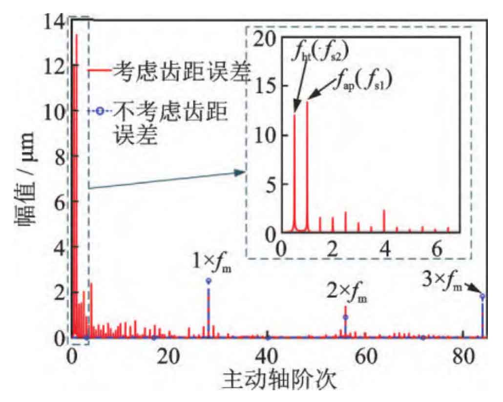
Figure 9 shows the dynamic transmission error spectrum after running 400 x 10 ^ 6 times. If the meshing non-uniformity caused by accumulated tooth pitch errors is not considered, the spectrum of worn gears only contains the meshing frequency component. The wear gear spectrum obtained by considering the cumulative error of tooth pitch contains a richer frequency component. In the low frequency range, obvious components such as chasing tooth frequency and combination state frequency can be observed, and there is also sideband frequency modulation phenomenon near the meshing frequency and its harmonics. Due to the particularity of the number of teeth in this example, the chasing tooth frequency fht is equal to the rotational frequency fs2 of the driven shaft, and the combined state frequency fap is equal to the rotational frequency fs1 of the active shaft.
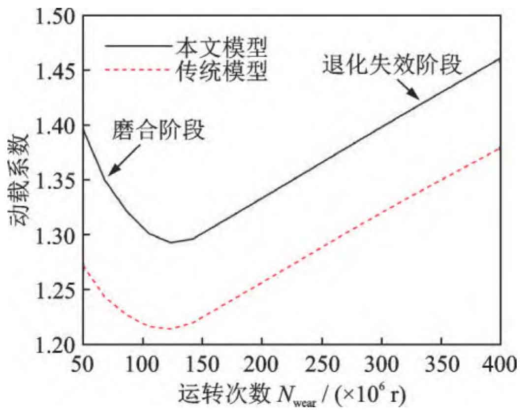
The dynamic load coefficients for different stages of wear degradation are shown in Figure 10. The dynamic load coefficient is defined as the ratio of the maximum dynamic meshing force to the static meshing force during the steady-state vibration cycle. In the early wear stage (running in stage), wear can play a role in improving the smoothness of meshing. The main reason is that slight wear can alleviate tooth interference during the process of alternating single and double teeth, playing a role in running in and passive shaping. As the number of runs increases, the meshing clearance (no-load transmission error) caused by wear becomes larger and larger, and the cylindrical gear system shows a clear trend of performance degradation, with a linear increase in vibration. Although both the model in this article and the traditional model (without considering tooth pitch error) can predict this performance degradation process, the traditional model will underestimate the dynamic load coefficient by about 10%.
3.3 Analysis of Uneven Wear
Traditional wear simulation analysis is based on uniform load distribution between cylindrical gear teeth, resulting in the same amount of wear on each tooth. However, in reality, due to the accumulation of tooth pitch errors, the wear morphology of each tooth surface is often different. After considering the cumulative error of tooth pitch, this model can effectively simulate the wear non-uniformity caused by the uneven load between the teeth of cylindrical gears. The wear distribution obtained by the model in this article is shown in Figure 11, and the colors in the cloud map represent the depth of tooth root wear on each gear tooth.
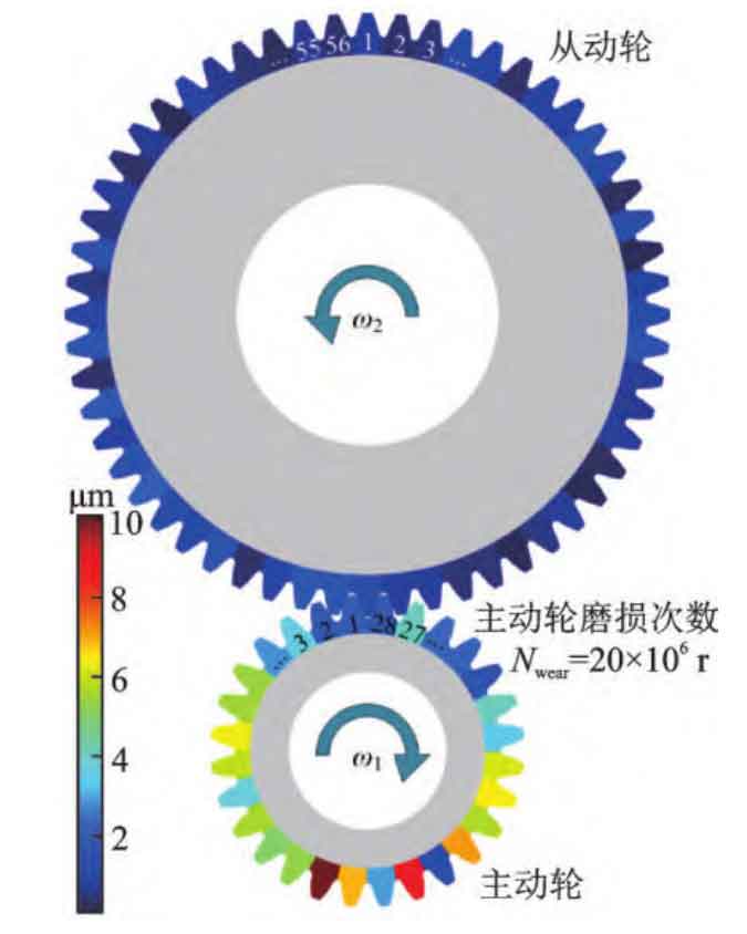
Due to the accumulation of tooth pitch errors in cylindrical gears, there is a significant difference in wear between the teeth of cylindrical gears. The wear of the driving wheel is generally greater than that of the driven wheel, because in a large cycle, the driving wheel engages more times than the driven wheel. The coefficient of wear non-uniformity is defined as the ratio of the standard deviation of the wear amount of each tooth to the average value:
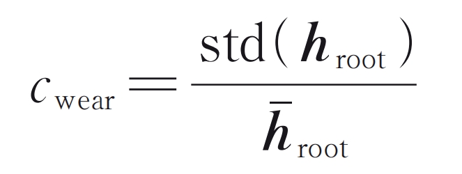
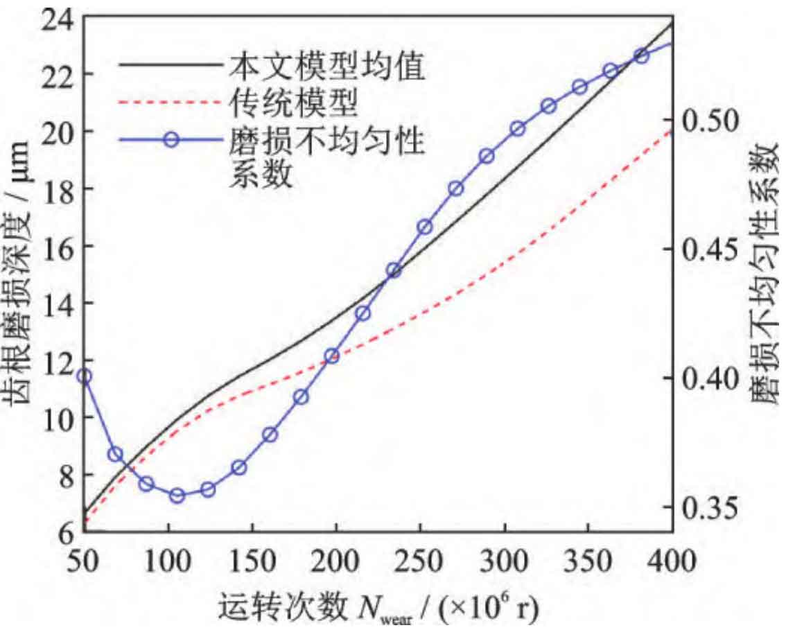
In the formula, hroot is the vector composed of the wear amount at the root position of each gear tooth. The root wear depth and wear non-uniformity coefficient of cylindrical gears at different wear stages are shown in Figure 12. The tooth root wear depth obtained by traditional models is only close to that of our model in the early stage of wear. As the wear degradation process progresses, the difference between our model and traditional models becomes increasingly significant. The difference between the two models is closely related to the uneven wear between teeth. The variation trend of the wear non-uniformity coefficient predicted by the model in this article is similar to that of the dynamic load coefficient. Early wear can help alleviate the uneven distribution of load between teeth caused by the pitch error of cylindrical gears, but severe wear can worsen the uniform load characteristics and contact state, leading to increased vibration and even failure.
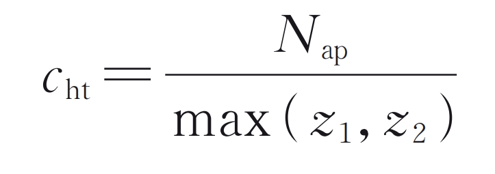
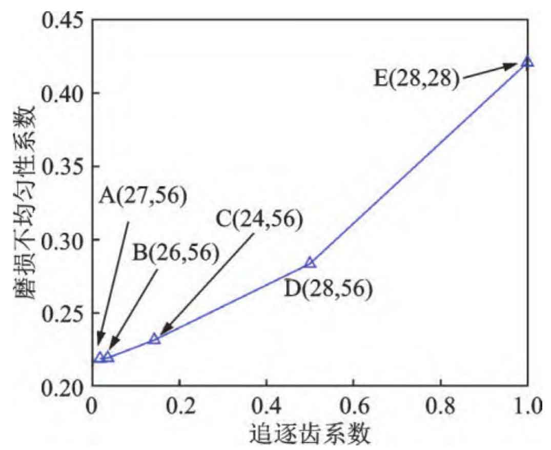
In order to study the wear distribution characteristics under different tooth number combinations, wear uniformity evaluations were conducted on the five tooth number combinations given in Table 3. The chase tooth coefficient is defined as:
| Tooth number combination | z1, z2 | Combination state coefficient | Combination state frequency/Hz | Chasing tooth coefficient | Chasing tooth frequency/Hz |
| A | 27, 56 | 1 | 1289.25 | 0.018 | 0.85 |
| B | 26, 56 | 2 | 620.75 | 0.036 | 1.71 |
| C | 24, 56 | 8 | 143.25 | 0.143 | 6.82 |
| D | 28, 56 | 28 | 47.75 | 0.5 | 23.88 |
| E | 28, 28 | 28 | 47.75 | 1 | 47.75 |
Figure 13 shows the variation law of the uniformity coefficient of driving wheel wear with the chasing tooth coefficient. From Figure 13, it can be seen that as the chasing tooth coefficient increases, the wear non-uniformity coefficient increases, that is, the difference in wear between teeth increases. For gear pair A, the number of teeth between the two gears is prime, and its coefficient of wear non-uniformity is the smallest. This is because when the number of teeth is coprime, the period (chasing tooth period) during which two specific teeth on the driving wheel and the driven wheel meet once is the longest. During the gear chasing cycle, the teeth of the driving wheel will mesh with each tooth of the driven wheel once. As the meshing process progresses, the wear between teeth gradually becomes more uniform. The design of two gears with a prime number of teeth is called a chasing tooth design. Compared to the original design (cylindrical gear pair D), the chase tooth design (gear pair A) can reduce the uneven wear coefficient by about 30%. For gear pair E, the teeth of the driving wheel will always mesh with one of the teeth of the driven wheel, which naturally causes severe wear of certain specific teeth. In the design process of cylindrical gears, the problem of chasing teeth should be fully considered to obtain a more uniform wear form and reduce the probability of local failure of cylindrical gears.
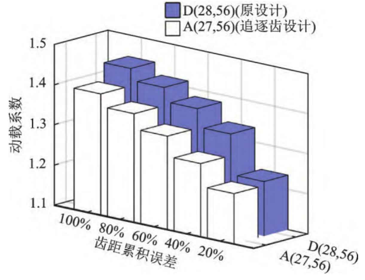
The dynamic load coefficients under different tooth pitch cumulative errors are shown in Figure 14. The cumulative error of tooth pitch in Figure 6 is defined as 100%. For different tooth pitch errors, the chase tooth design can effectively reduce vibration. When the machining accuracy of cylindrical gears is high (see 20% cumulative error of tooth pitch in Figure 14), the difference in vibration response between the chase tooth design and the original design is small. Due to limitations such as transmission ratio and structural dimensions, not all cylindrical gears in engineering can meet the requirements of chasing tooth design. When the accumulated error of the tooth pitch of cylindrical gears is small, the requirement for chasing tooth design can be appropriately relaxed.
4. Conclusion
A dynamic wear prediction model for cylindrical gears considering cumulative tooth pitch error is proposed based on the contact analysis method of gear teeth, the rotor dynamics model of cylindrical gears, and the Archard wear model. The effectiveness of the model was verified by comparing the simulated spectrum with literature experiments. Based on the above model, the impact of accumulated tooth pitch error on response characteristics and wear distribution was analyzed, and the main conclusions are as follows:
(1) The cumulative error of cylindrical gear tooth pitch will introduce rich frequency components such as shaft rotation frequency, chasing tooth frequency, and combination state frequency to meshing stiffness, transmission error, and vibration response. However, the spectrum obtained from traditional dynamic models generally only contains the meshing frequency component.
(2) The model can evaluate the unevenness of inter tooth wear caused by the cumulative error of cylindrical gear pitch, improving the idealized assumption in traditional wear models that the wear amount of each gear tooth is equal. Mild wear can help alleviate uneven load distribution between teeth, but severe wear can worsen the uniform load characteristics, leading to increased vibration.
(3) The dynamic wear model can establish a mapping relationship between the chase tooth coefficient and the wear non-uniformity coefficient. The use of chasing teeth design can reduce the uneven wear coefficient by about 30%. When the cumulative error of the tooth pitch of cylindrical gears is small, the requirement for the design of chasing teeth can be appropriately relaxed.