
In the field of industrial robotics, precision and reliability are paramount. The rotary vector reducer, commonly known as the RV reducer, has emerged as a critical component due to its high transmission ratio, efficiency, load capacity, and minimal backlash. As a two-stage closed planetary gear system, the rotary vector reducer integrates an involute gear stage and a cycloidal gear stage, making it ideal for applications in machinery, aviation, and manufacturing. However, the dynamic behavior of the rotary vector reducer under operational conditions can significantly impact performance, leading to vibrations that affect transmission accuracy and longevity. Therefore, a thorough investigation into the torsional dynamics of the rotary vector reducer is essential for optimizing design and ensuring robust operation. This article presents a comprehensive analysis using a lumped parameter approach, considering time-varying meshing stiffness and damping effects, to derive the natural characteristics and dynamic responses of an RV320E-type rotary vector reducer. The findings are validated through experimental tests, providing a foundation for structural improvements and fault diagnosis in rotary vector reducer systems.
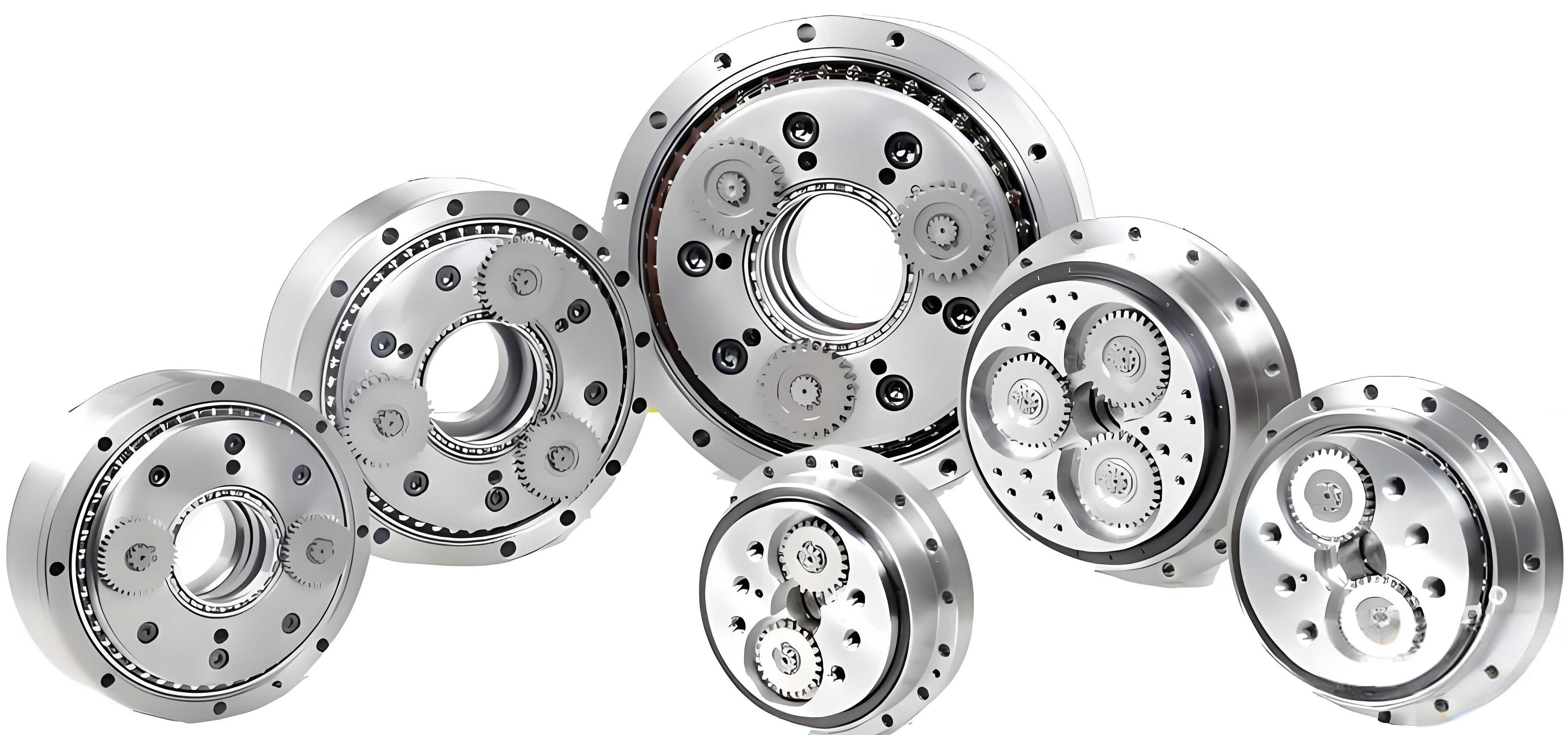
The rotary vector reducer’s structure comprises several key components: a sun gear, planetary gears, cycloidal gears, crank shafts, a pin gear housing, and an output mechanism. The first stage involves an involute gear reduction where the sun gear, driven by a motor, engages with multiple planetary gears. These planetary gears then transmit motion to the crank shafts, which drive the cycloidal gears in the second stage. The cycloidal gears mesh with pin gears, converting eccentric motion into rotational output via the crank shafts and output mechanism. This complex interaction introduces dynamic forces that necessitate detailed modeling. To capture the torsional dynamics, I employ a lumped parameter method, treating each rotating component as a concentrated mass with rotational degrees of freedom. The system is simplified into eight degrees of freedom, accounting for the sun gear, three planetary gears, two cycloidal gears, the input shaft, and the output shaft. This model allows for the formulation of torsional vibration equations that incorporate stiffness and damping parameters specific to the rotary vector reducer.
The torsional dynamics model is represented by a set of differential equations derived from Newton’s second law. For each component, the equation balances inertial forces with elastic and damping forces from meshing interactions. The general form for the system can be expressed as:
$$ M \ddot{x} + C \dot{x} + K x = F(t) $$
where \( M \) is the mass matrix, \( C \) is the damping matrix, \( K \) is the stiffness matrix, \( x \) is the displacement vector, and \( F(t) \) is the external force vector. For the rotary vector reducer, the matrices are populated based on the connections between components. The stiffness matrix includes time-varying meshing stiffnesses for both gear stages, which are critical for accurate dynamic prediction. The damping matrix accounts for energy dissipation at contact points, such as between gears and shafts. To illustrate the parameters, Table 1 summarizes key symbols and their meanings used in the modeling of the rotary vector reducer.
| Symbol | Description | Value/Unit |
|---|---|---|
| \( b \) | Width of single tooth deformation zone | 12 mm |
| \( E \) | Elastic modulus of cycloidal gear and pin gear | 2.06 × 10⁵ MPa |
| \( \mu \) | Poisson’s ratio of cycloidal gear | 0.3 |
| \( r_c \) | Effective radius of cycloidal gear | Derived from geometry |
| \( r_{hp} \) | Effective radius of planetary gear | 5 mm |
| \( K \) | Meshing stiffness | Time-varying, N/m |
| \( C \) | Damping coefficient | Dimensionless or N·s/m |
| \( M \) | Equivalent mass | kg |
| \( \omega \) | Angular velocity | rad/s |
The time-varying meshing stiffness in the involute gear stage is modeled using Fourier series expansion to account for periodic changes due to tooth engagement. For a gear pair, the stiffness \( k(t) \) can be expressed as:
$$ k(t) = k_0 + \sum_{n’=1}^{N} k_1 \cos(n’ \omega_m t + \phi) $$
where \( k_0 \) is the average meshing stiffness, \( k_1 \) is the harmonic amplitude, \( \omega_m \) is the gear meshing frequency, and \( \phi \) is the phase angle. The parameters \( k_0 \) and \( k_1 \) depend on the single-tooth stiffness \( k_{m1} \) and double-tooth stiffness \( k_{m2} \), as well as the contact ratio \( \epsilon \). Specifically:
$$ k_0 = k_{m1}(\epsilon – 1) + k_{m2}(2 – \epsilon) $$
$$ k_1 = \frac{2(k_{m1} – k_{m2})}{n \pi} \sin[(2 – \epsilon) n’ \pi] $$
$$ \phi = (2 – \epsilon) n’ \pi $$
For the cycloidal gear stage in the rotary vector reducer, the meshing stiffness is more complex due to multiple simultaneous tooth contacts. The single-tooth stiffness \( k_i \) for a cycloidal gear interacting with a pin gear is derived from Hertzian contact theory and geometric considerations:
$$ k_i = \frac{\pi b E r_{hp} s}{4(1 – \mu^2)(r_{hp} s + 2 r_{hp} T)} $$
where \( s \) is the length of the meshing line, and \( T \) is a geometric parameter related to the cycloid profile. The total equivalent torsional stiffness for the cycloidal stage is obtained by summing the contributions from all engaged teeth, considering the effective radius. This stiffness is crucial for the dynamic behavior of the rotary vector reducer. The overall system stiffness matrix \( K \) combines these time-varying elements, leading to a parametrically excited system.
To analyze the natural characteristics, I first simplify the time-varying stiffness by replacing it with its average value over a meshing cycle. This approximation allows the free vibration equation to be solved for natural frequencies and mode shapes. The equation becomes:
$$ M \ddot{x} + K_{avg} x = 0 $$
Assuming harmonic motion \( x = \Psi \cos(\omega t – \theta) \), the eigenvalue problem is:
$$ (K_{avg} – \omega_i^2 M) \Psi_i = 0 $$
Solving this yields the natural frequencies \( \omega_i \) and corresponding mode shapes \( \Psi_i \) for the rotary vector reducer. Table 2 lists the first eight natural frequencies calculated for the RV320E model, highlighting the dynamic modes relevant to the rotary vector reducer.
| Mode Order | Natural Frequency (Hz) |
|---|---|
| 1 | 906 |
| 2 | 1,771 |
| 3 | 4,749 |
| 4 | 6,592 |
| 5 | 8,234 |
| 6 | 8,249 |
| 7 | 9,471 |
| 8 | 36,946 |
The mode shapes reveal distinct vibration patterns. For instance, the first mode often involves rigid body motion, while higher modes exhibit complex interactions between gears. Table 3 provides a simplified representation of mode shape vectors for key components at selected frequencies, illustrating how different parts of the rotary vector reducer participate in each mode.
| Component | Mode 1 (906 Hz) | Mode 2 (1,771 Hz) | Mode 3 (4,749 Hz) |
|---|---|---|---|
| Sun Gear | 1.000 | -0.280 | 0.300 |
| Planetary Gear 1 | -0.020 | -1.000 | 0.120 |
| Cycloidal Gear 1 | 0.000 | 0.500 | 0.037 |
| Output Shaft | 0.000 | -0.035 | 1.000 |
These results indicate that the sun gear and output shaft are highly involved in multiple modes, suggesting potential areas for design optimization in the rotary vector reducer. The closeness of some frequencies, such as modes 5 and 6, may lead to modal coupling, exacerbating vibrations under certain conditions.
Next, I investigate the dynamic response of the rotary vector reducer under operational speeds. Using numerical methods like the Runge-Kutta algorithm, I solve the full torsional equations with time-varying stiffness and damping. The damping coefficient is initially set to 0.03, and responses are computed for input speeds of 500, 800, and 1000 rpm. The displacement and velocity of key components, such as the sun gear, planetary gears, and cycloidal gears, are extracted to assess vibration levels. For example, the vibration displacement \( X \) for the sun gear can be expressed as a function of time, influenced by the meshing forces in the rotary vector reducer.
The results show that vibration amplitudes generally increase with speed, though not linearly. At 500 rpm, the peak displacement of the sun gear is around 4.94 μm, while the cycloidal gears exhibit lower displacements due to multiple tooth engagement. Table 4 summarizes the root mean square (RMS) values of vibration displacement for critical components across different speeds, emphasizing the behavior of the rotary vector reducer.
| Component | 500 rpm (μm) | 800 rpm (μm) | 1000 rpm (μm) |
|---|---|---|---|
| Sun Gear | 4.94 | 5.12 | 5.45 |
| Planetary Gear 1 | 1.44 | 1.52 | 1.60 |
| Cycloidal Gear 1 | 1.60 | 1.65 | 1.72 |
| Output Shaft | 3.27 | 3.40 | 3.55 |
To explore damping effects, I repeat the analysis with a damping coefficient of 0.06. The vibration amplitudes decrease significantly, highlighting the importance of damping in controlling dynamic responses in the rotary vector reducer. For instance, at 1000 rpm, the sun gear displacement reduces by approximately 15% with higher damping. This underscores the need for proper material selection and lubrication in rotary vector reducer designs to mitigate vibrations.
The vibration velocity responses further illustrate dynamic trends. The velocity \( \dot{x} \) is derived from the displacement solutions and shows similar speed-dependent behavior. At higher speeds, the velocity peaks increase, indicating greater kinetic energy fluctuations. This can lead to noise and wear in the rotary vector reducer if not addressed. The mathematical relation for velocity is integrated from the acceleration, which is directly obtained from the dynamics equations:
$$ \dot{x}(t) = \int \ddot{x}(t) \, dt $$
where \( \ddot{x}(t) \) is computed from \( M^{-1}(F(t) – C \dot{x} – K x) \).
For experimental validation, I set up a test rig using an RV320E rotary vector reducer coupled with a motor and load. Acceleration sensors are mounted on the reducer housing to capture vibration signals. The tests are conducted at speeds of 500, 800, 1000, 1200, and 1500 rpm. The acquired acceleration data are processed to obtain vibration velocities and displacements for comparison with theoretical predictions. Table 5 presents the peak acceleration values from experiments, showing a clear increase with speed, consistent with the dynamic model of the rotary vector reducer.
| Speed (rpm) | Peak Acceleration (g) |
|---|---|
| 500 | 0.12 |
| 800 | 0.24 |
| 1000 | 0.59 |
| 1200 | 1.21 |
| 1500 | 1.60 |
The experimental results align well with the simulated responses, confirming the accuracy of the torsional dynamics model for the rotary vector reducer. Discrepancies are minimal, primarily due to assumptions like simplified damping and stiffness averaging. However, the model effectively captures key trends, such as the rise in vibration with speed and the relative magnitudes among components. This validation reinforces the utility of the lumped parameter approach for analyzing complex systems like the rotary vector reducer.
In conclusion, this study provides a detailed dynamics analysis of the rotary vector reducer through modeling and experimentation. The torsional model, incorporating time-varying meshing stiffness and damping, successfully predicts natural frequencies and dynamic responses. The rotary vector reducer exhibits distinct vibration modes, with the sun gear and output shaft being particularly susceptible to oscillations. Increasing rotational speed generally amplifies vibrations, while higher damping coefficients can mitigate these effects. The experimental tests corroborate the theoretical findings, demonstrating the model’s reliability for applications in design optimization and fault diagnosis. Future work could explore nonlinearities such as backlash and manufacturing errors to further refine the dynamics understanding of the rotary vector reducer. Overall, this research underscores the importance of dynamic analysis in enhancing the performance and durability of rotary vector reducers in industrial robotics and beyond.