1. Introduction
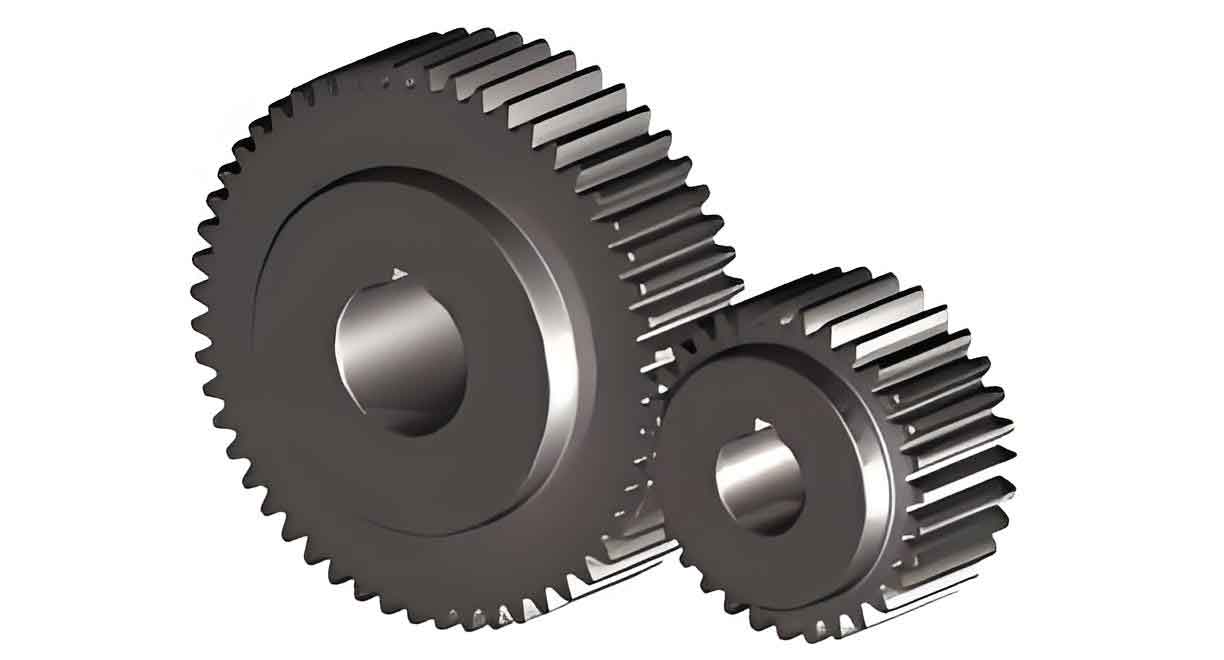
Spur gear is fundamental components in mechanical transmission systems, widely used due to their simplicity, high efficiency, and reliability. However, their dynamic behavior, influenced by factors such as rotational speed and mesh stiffness, remains a critical area of study. Mesh stiffness, a key parameter reflecting a gear pair’s resistance to deformation, directly governs vibration, noise, and fatigue life. Traditional methods for calculating mesh stiffness often neglect rotational speed effects, leading to inaccuracies in predicting dynamic responses. This study addresses this gap by proposing a rotational speed-dependent dynamic mesh stiffness algorithm and analyzing its impact on spur gear dynamics.

2. Methodology
2.1 Dynamic Mesh Stiffness Calculation
The dynamic mesh stiffness of spur gear was computed using an improved finite element method (FEM) framework integrated with the average acceleration method. A single-tooth model (Fig. 1) simplified the meshing process, assuming fixed boundary conditions at the gear’s inner bore. The governing equation for gear dynamics is:MX¨i+CX˙i+KXi=FiMX¨i+CX˙i+KXi=Fi
where:
- M,C,KM,C,K: Mass, damping, and stiffness matrices.
- FiFi: Time-varying excitation force matrix.
- α,βα,β: Rayleigh damping coefficients.
The meshing speed vivi at the ii-th contact point is defined as:vi=πθ˙pxi2+yi230vi=30πθ˙pxi2+yi2
where θ˙pθ˙p is the rotational speed of the driving gear. The average meshing speed between adjacent points is:va=vi+vi+12va=2vi+vi+1
Dynamic deformation ΔxiΔxi and ΔyiΔyi were iteratively solved using the average acceleration method. Single-tooth stiffness kpikpi and kgikgi for driving and driven gears were derived as:kpi=FiΔxicos(π2−βi)+Δyicosβikpi=Δxicos(2π−βi)+ΔyicosβiFi
The total dynamic mesh stiffness kmskms for spur gear is:kms=11kpi+1kgikms=kpi1+kgi11
2.2 Spur Gear Dynamic Model
A two-degree-of-freedom (2-DOF) lumped parameter model (Fig. 2) was developed to analyze torsional vibrations. The equations of motion are:Jpθ¨p+Rbp∑j=1nFmj−∑j=1nRfpjFfj=TpJpθ¨p+Rbpj=1∑nFmj−j=1∑nRfpjFfj=TpJgθ¨g+Rbg∑j=1nFmj+∑j=1nRfgjFfj=−TgJgθ¨g+Rbgj=1∑nFmj+j=1∑nRfgjFfj=−Tg
where:
- Jp,JgJp,Jg: Moments of inertia.
- Rbp,RbgRbp,Rbg: Base circle radii.
- FmjFmj: Dynamic meshing force, expressed as Fmj=kmjδ(t)+cmjδ˙(t)Fmj=kmjδ(t)+cmjδ˙(t).
3. Results and Analysis
3.1 Validation of Dynamic Mesh Stiffness
The proposed method was validated against static stiffness results from ANSYS and the potential energy method (PEM). Key parameters of the spur gear pair are summarized in Table 1.
Table 1: Spur Gear Pair Parameters
| Parameter | Driving Gear | Driven Gear |
|---|---|---|
| Number of Teeth | 23 | 47 |
| Mass (kg) | 0.21 | 0.37 |
| Elastic Modulus (GPa) | 211 | 211 |
| Pressure Angle (°) | 20 | 20 |
| Module (mm) | 2.5 | 2.5 |
Key Observations:
- At near-static conditions (θ˙p=0.01 r/minθ˙p=0.01r/min), dynamic stiffness converged to static values (Fig. 4).
- At θ˙p=1,300 r/minθ˙p=1,300r/min, dynamic stiffness exhibited fluctuations due to forced vibrations (Fig. 5).
3.2 Rotational Speed Effects on Mesh Stiffness
Dynamic mesh stiffness variations under different speeds are compared in Fig. 6–7. Key trends include:
- Amplitude Fluctuation: Higher rotational speeds amplified stiffness oscillations (Table 2).
- Resonance Shift: Resonance regions predicted by dynamic stiffness diverged from static models.
- Superharmonic Response: High-speed conditions (>5,000 r/min>5,000r/min) intensified nonlinear vibrations.
Table 2: Dynamic vs. Static Stiffness Fluctuation
| Rotational Speed (r/min) | Fluctuation Amplitude (×103 N/m×103N/m) |
|---|---|
| 500 | 1.2 |
| 1,300 | 3.5 |
| 5,000 | 7.8 |
| 9,500 | 12.4 |
3.3 Dynamic Response Analysis
Bifurcation diagrams (Fig. 13) revealed distinct vibration modes:
- Low Speed (<2,000 r/min<2,000r/min): Stable 1-periodic motion.
- Medium Speed (3,000–6,000 r/min3,000–6,000r/min): Chaotic behavior with multi-periodic orbits.
- High Speed (>7,000 r/min>7,000r/min): Stabilized 2-periodic motion.
Dynamic transmission error (DTE) and frequency spectra (Fig. 8–12) highlighted speed-dependent nonlinearities, such as subharmonic resonances and sideband modulation.
4. Discussion
4.1 Implications for Spur Gear Design
- Vibration Control: Dynamic stiffness models improve resonance prediction, aiding in speed range optimization.
- Noise Reduction: High-speed fluctuations correlate with acoustic emissions; damping strategies must account for rotational effects.
- Fatigue Life: Cyclic stiffness variations accelerate crack initiation; load distribution analysis is critical.
4.2 Limitations and Future Work
- Model Simplifications: The single-tooth assumption neglects multi-tooth interactions.
- Experimental Validation: Laboratory tests under varying speeds are needed.
- Extended Applications: The algorithm could be adapted for helical or bevel gears.
5. Conclusion
This study establishes a rotational speed-dependent dynamic mesh stiffness algorithm for spur gear, bridging gaps in traditional static models. Key findings include:
- Dynamic stiffness fluctuates with speed, intensifying at higher rotations.
- Resonance regions shift significantly compared to static predictions.
- Nonlinear vibrations dominate at medium-to-high speeds, necessitating advanced control strategies.
By integrating dynamic stiffness into gear design, engineers can enhance transmission efficiency, reduce noise, and prolong service life. Future work will focus on experimental validation and extending the model to complex gear geometries.
