Preset transmission error curve
The vibration and noise generated by gear meshing mainly come from the transmission error of gear, and the transmission error also reflects the meshing quality of tooth surface to a certain extent. Therefore, the second-order parabola is proposed as the basic line shape of transmission error curve, as shown in Fig. 1, where Z1 and Z2 are the number of matched small wheels and big teeth, then 2 π / Z2 can be expressed as angular displacement of single tooth meshing of large wheel; the independent variable φ 2 is the angular displacement of large wheel, and the dependent variable Δ φ 1 is the error error error of pinion transmission, which is the second-order function of angular displacement of large gear; and φ 2n, φ 2m, and φ 2p are the angular displacement of large gear They are the angular displacements of the large wheel when entering the meshing point n, the reference point m and the exiting meshing point P respectively, and δ te is the maximum error in the gear meshing transmission.

According to Fig. 1, the motion relationship between the big wheel and the small wheel can be obtained, as shown in the formula. In the formula, Δ φ 1 (φ 2) is the function curve of the preset transmission error with respect to the rotation angle of the big wheel, and Δ φ 1 and Δ φ 2 are the initial angular displacement of the small wheel and the big wheel.

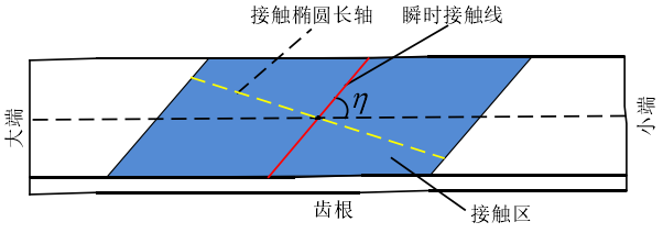
Preset contact mark
To some extent, the shape of the contact mark on the tooth surface depends on the manufacturing and installation errors of the gear. The contact mark area is controlled on the projection surface of the gear. In order to facilitate the design, the instantaneous contact line of the tooth surface is preset as a straight line (in fact, the instantaneous contact line is not a straight line), η is the angle between the proposed contact track and the gear tooth width direction, and the preset contact ellipse long axis is not actually a straight line. The contact mark area is controlled in the area of 40% ~ 60% of the tooth width direction at the center of the tooth surface, as shown in Fig. 2.