
In my daily work on mechanical transmission systems, I have repeatedly encountered the challenge of maintaining proper meshing clearance in rack and pinion gears. Mechanical transmission is the use of mechanical means to transfer power and motion. A mechanical transmission mechanism can change the mode, direction, or speed of motion provided by a power source so that it can be used purposefully. Among the main transmission types, gear transmission, belt transmission, and chain transmission are the most common. Within gear transmission, rack and pinion gears form a special and highly practical category because they convert rotary motion into linear motion or linear motion into rotary motion. I have found that the adjustment of meshing clearance in rack and pinion gears directly affects transmission accuracy, efficiency, reliability, and service life.
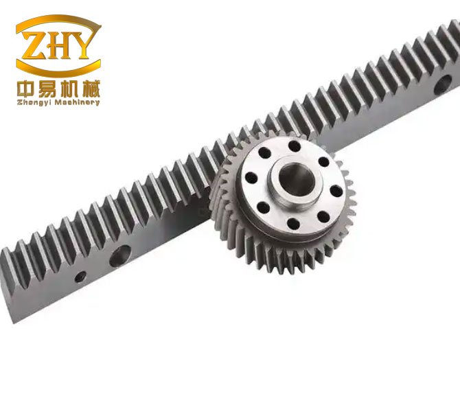
Rack and pinion gears are widely used in modern equipment. A rack and pinion gear set can transmit motion and power through the meshing of a gear with a rack. The gear is circular, while the rack is long and straight. The tooth profile of the gear is a curve, usually an involute, while the tooth profile of the rack is a straight line. The motion of the gear is rotation, that is, circular motion, while the motion of the rack is translation, that is, linear motion. When the gear acts as the driving member, it meshes with the rack and drives a component to perform linear motion. This characteristic makes rack and pinion gears especially suitable for applications such as machine tool feeds, automated guided vehicles, sanding trolleys, 3D printing sand supply systems, and many other positioning and transport mechanisms.
In my research and practical design experience, I have observed that the meshing clearance of rack and pinion gears is influenced by three main factors: the accuracy of the gear itself, the machining accuracy of the processed parts, and the assembly accuracy. Even when the gear quality and frame machining meet requirements, the final service effect and life of rack and pinion gears depend heavily on assembly precision. This is why I have devoted considerable attention to the clearance adjustment method. A well-designed adjustment mechanism can reduce unnecessary operations during installation and maintenance, improve transmission stability, and lower the total cost of ownership.
The transmission accuracy of rack and pinion gears is directly affected by the meshing clearance. If the clearance is too large, backlash increases, positioning accuracy decreases, and impact loads may occur during reversal. If the clearance is too small, the teeth may interfere, friction and heat may increase, and the risk of seizure or accelerated wear may rise. Therefore, I treat the clearance of rack and pinion gears as a critical design parameter rather than an afterthought. In my experience, the ideal adjustment method should be simple, repeatable, precise, and cost-effective. It should allow the maintenance personnel to adjust the clearance without completely disassembling the transmission assembly.
At present, I have identified three common forms of clearance adjustment for rack and pinion gears: slotted hole plus bolt adjustment, precision shim adjustment, and eccentric wheel adjustment. Each method has its own advantages and limitations. I have compared these methods in detail, and I have proposed an eccentric pin structure that simplifies the adjustment process. My goal is to solve the problem of cumbersome adjustment of the meshing clearance between the gear and the rack, simplify unnecessary operations during clearance adjustment, and achieve convenient installation and maintenance.
To describe the geometry of rack and pinion gears, I often begin with the basic relationship between the gear and the rack. For a standard spur gear meshing with a rack, the pitch circle of the gear rolls without slipping on the pitch line of the rack. The linear displacement of the rack is related to the angular displacement of the gear by the following equation:
$$s = r \theta$$
where \(s\) is the linear displacement of the rack, \(r\) is the pitch radius of the gear, and \(\theta\) is the angular displacement of the gear in radians. The corresponding linear velocity is:
$$v = r \omega$$
where \(v\) is the linear velocity of the rack and \(\omega\) is the angular velocity of the gear. These relationships are fundamental to the design of any transmission system using rack and pinion gears. They also show that any change in the center distance between the gear and the rack can alter the effective meshing condition and therefore the backlash.
The center distance between the gear and the rack is not a conventional center distance between two gears, because the rack has an infinite radius. Instead, the key geometric parameter is the distance from the gear center to the rack pitch line. Let this distance be \(a\). For a gear with module \(m\) and number of teeth \(z\), the pitch radius is:
$$r = \frac{m z}{2}$$
The rack pitch line is located at a distance \(a\) from the gear center. When the gear and rack are correctly meshed, the gear pitch circle is tangent to the rack pitch line, so \(a = r\) for a standard zero-backlash condition without backlash. In practice, a small amount of backlash is required to compensate for manufacturing errors, thermal expansion, and lubrication. The circumferential backlash \(j_t\) is related to the normal backlash \(j_n\) by the pressure angle \(\alpha\):
$$j_n = j_t \cos \alpha$$
For a small change in the center distance \(\Delta a\), the normal backlash changes approximately as:
$$j_n \approx 2 \Delta a \tan \alpha$$
This equation is important because it shows that the clearance of rack and pinion gears is very sensitive to center distance changes. For example, if the pressure angle is \(20^\circ\) and the center distance changes by \(0.1\) mm, the normal backlash changes by approximately \(0.0728\) mm. This sensitivity is one reason why precise adjustment mechanisms are necessary for rack and pinion gears.
I have also examined the sources of error in rack and pinion gears. The first source is the gear itself. Gear accuracy includes pitch deviation, profile deviation, helix deviation, and runout. The second source is the machining accuracy of the components that carry the gear and the rack, such as the motor mounting plate, support plate, guide rail platform, and bearing seats. The third source is assembly accuracy, which includes parallelism, perpendicularity, and center distance adjustment. When I design a clearance adjustment method for rack and pinion gears, I must consider all three sources. However, in many practical cases, the gear quality and machining quality are already fixed by the supplier and the manufacturing process. Therefore, the assembly and adjustment method becomes the most controllable factor.
In my experience, the most common adjustment method for rack and pinion gears is the slotted hole plus bolt adjustment. This method uses slotted holes on a mounting plate and bolts to adjust the center distance between the gear and the rack. The structure is simple, the adjustment is convenient, and the machining requirements for the workpiece are not high. The cost is relatively low, so it is often the first choice. The working principle is to adjust the center distance between the gear and the rack through bolts on the upper and lower sides. Although this seems simple, in reality, a dial indicator or other precision tool is often needed to determine whether the meshing clearance of the rack and pinion gears meets the requirement. In many factories, workers still rely on their feeling to adjust the clearance. I believe this is risky because the service effect and life of rack and pinion gears depend greatly on assembly precision.
The second common method is precision shim adjustment. This method requires selecting shims according to the design structure. The workload may appear large, but the adjustment precision is relatively accurate. Usually, two to three adjustments are enough to complete the process, so the efficiency can be high. However, the technical requirements for the assembly personnel are also high. The working principle is to add or remove precision shims between the mounting bracket and the sliding table, or to replace shims of different thicknesses, in order to adjust the clearance. When using this method to adjust the clearance of rack and pinion gears, I recommend using a dial indicator or other precision tool to detect the clearance. It is not advisable to adjust by feeling. The contact surface has high machining accuracy requirements, and the perpendicularity of the mounting bracket should be designed with a tolerance requirement to ensure that the parallelism of the rack and pinion gears meets the design standard.
The third common method is eccentric wheel adjustment. This method is mainly used in heavy-load occasions. The adjustment difficulty is relatively high, but it is often the first design choice for many applications. The structure is simple, the adjustment is convenient, and the machining requirements are not high. The cost is relatively low. The working principle is that the fixed screw holes of the intermediate gear and the eccentric wheel have a center offset, so the eccentric wheel changes the center distance between the gear and the rack at different positions. By rotating the eccentric wheel to match different screw holes on the sliding table, the clearance of the rack and pinion gears can be adjusted. When the eccentricity is smaller, the adjustment precision is higher, and the machining requirements for the parts are also higher. This method has the highest machining accuracy requirements and the highest overall cost, but its load-bearing capacity is outstanding.
I have summarized the comparison of these three methods in the following table. The table includes the adjustment principle, precision, operation difficulty, cost, machining requirement, and typical application for rack and pinion gears.
| Adjustment Method | Principle | Adjustment Precision | Operation Difficulty | Cost | Machining Requirement | Typical Application |
|---|---|---|---|---|---|---|
| Slotted hole plus bolt | Adjust center distance by bolts in slotted holes | Medium | Low to medium | Low | Low | General machinery, light loads |
| Precision shim | Add or remove shims to change center distance | High | Medium to high | Medium | High | Precision equipment, medium loads |
| Eccentric wheel | Rotate eccentric wheel to change center distance | High | High | High | Very high | Heavy loads, high rigidity |
| Eccentric pin | Rotate eccentric pin to translate motor plate | High and repeatable | Low | Low | Medium | Rack and pinion gears in automated systems |
From this table, I can see that each method has a specific field of application. However, for rack and pinion gears in automated systems such as 3D printing sand supply systems, I have found that the eccentric pin method offers a better balance of precision, cost, and ease of operation. The eccentric pin method is different from the eccentric wheel method. In the eccentric wheel method, the entire eccentric wheel rotates and drives the motor connection plate and the motor to rotate and move. In the eccentric pin method, the rotation of the eccentric pin drives the motor connection plate and the motor to translate in parallel. The source of adjustment is only the rotation of the eccentric pin, so the operation is simpler.
I will now describe the structure of my proposed eccentric pin adjustment device for rack and pinion gears. The device includes a motor, a motor connection plate, an eccentric pin, a lock nut, a gear, a guide rail platform, a rack, a support plate, and fastening bolts. The motor is connected to the motor connection plate by bolts, and this connection is fixed and locked. The motor connection plate has an oval adjustment hole. The support plate has a threaded hole. The motor connection plate and the support plate are connected by fastening bolts, and this connection is adjustable. Before adjusting the clearance of the rack and pinion gears, the fastening bolts are not locked. The eccentric pin is inserted through the motor connection plate and the support plate. The contact area between the eccentric pin and the connection plate is an eccentric cylinder. Rotating the eccentric pin changes its angular position, and this rotation drives the motor connection plate to translate. The relative position of the oval adjustment hole on the motor connection plate and the threaded hole on the support plate changes. When the clearance between the gear and the rack is appropriate, the eccentric pin is fixed by the lock nut, and the fastening bolts are tightened. The gear is connected to the motor, and this connection is coaxial. The motor drives the gear to rotate. The rack is fixed on the guide rail platform, and the guide rail platform and the rack cannot move.
In my design, the motor, the motor connection plate, and the gear are connected together. The motor connection plate and the support plate are connected by the eccentric pin and the fastening bolts. By rotating the eccentric pin, the eccentric structure drives the motor connection plate to translate. Therefore, the motor and the gear also translate correspondingly, and the clearance between the gear and the rack changes. This is the core principle of my adjustment method for rack and pinion gears. The advantage of this method is that the fastening bolts only need to be loosened, not completely removed. After the eccentric pin is rotated by a certain angle and the clearance meets the precision requirement, all relevant bolts can be locked. The operation is simple and the cost is saved.
To analyze the eccentric pin mechanism mathematically, I define the eccentricity of the pin as \(e\). The initial angular position of the eccentric pin is \(\theta_0\), and the rotation angle applied during adjustment is \(\theta\). The displacement of the motor connection plate in the horizontal direction is:
$$\Delta x = e \left[ \cos(\theta_0 + \theta) – \cos \theta_0 \right]$$
The displacement in the vertical direction is:
$$\Delta y = e \left[ \sin(\theta_0 + \theta) – \sin \theta_0 \right]$$
The total displacement magnitude is:
$$\Delta s = \sqrt{\Delta x^2 + \Delta y^2}$$
For small rotation angles, the displacement can be approximated by a linear relationship. If \(\theta\) is small, then:
$$\Delta x \approx -e \theta \sin \theta_0$$
$$\Delta y \approx e \theta \cos \theta_0$$
The magnitude is approximately:
$$\Delta s \approx e \theta$$
This linear approximation is useful for estimating the adjustment sensitivity. The sensitivity of the eccentric pin, defined as the displacement per unit rotation angle, is:
$$\frac{d s}{d \theta} = e$$
If the rotation angle is measured in degrees, the displacement per degree is:
$$\Delta s_{1^\circ} = e \frac{\pi}{180}$$
For example, if the eccentricity is \(e = 2\) mm, then the displacement per degree is approximately \(0.0349\) mm. This means that a small rotation of the eccentric pin can produce a fine adjustment of the center distance between the gear and the rack. In my experience, this level of sensitivity is suitable for precise clearance adjustment of rack and pinion gears.
The relationship between the rotation angle of the eccentric pin and the resulting clearance change can be summarized in a table. The following table shows the calculated displacement for different eccentricities and rotation angles. The values are based on the small-angle approximation \(\Delta s \approx e \theta\) with \(\theta\) converted to radians.
| Eccentricity \(e\) (mm) | Rotation angle (degrees) | Rotation angle (radians) | Approximate displacement (mm) | Approximate clearance change (mm) |
|---|---|---|---|---|
| 1.0 | 1 | 0.01745 | 0.0175 | 0.0127 |
| 1.0 | 5 | 0.08727 | 0.0873 | 0.0635 |
| 1.0 | 10 | 0.17453 | 0.1745 | 0.1270 |
| 2.0 | 1 | 0.01745 | 0.0349 | 0.0254 |
| 2.0 | 5 | 0.08727 | 0.1745 | 0.1270 |
| 2.0 | 10 | 0.17453 | 0.3491 | 0.2541 |
| 3.0 | 1 | 0.01745 | 0.0524 | 0.0381 |
| 3.0 | 5 | 0.08727 | 0.2618 | 0.1905 |
| 3.0 | 10 | 0.17453 | 0.5236 | 0.3811 |
In this table, the approximate clearance change is calculated from the displacement using the relation \(j_n \approx 2 \Delta a \tan \alpha\) with a pressure angle of \(20^\circ\). This demonstrates how the eccentric pin can adjust the meshing clearance of rack and pinion gears in a controlled manner. I have used this table in my design work to select the eccentricity and the expected rotation range. For a typical application, an eccentricity of 1.5 to 2.5 mm provides a good balance between adjustment range and sensitivity.
I have also considered the locking and fastening of the eccentric pin. The eccentric pin must be locked after adjustment to prevent rotation under vibration and dynamic loads. The lock nut provides a clamping force that generates friction between the pin and the support plate. The relationship between the tightening torque \(T\) and the axial clamping force \(F\) is approximately:
$$T = K F d$$
where \(K\) is the nut factor, \(F\) is the clamping force, and \(d\) is the nominal thread diameter. For a lubricated steel thread, \(K\) is typically between 0.15 and 0.20. If the required clamping force is 5 kN and the thread diameter is 10 mm, the required torque is approximately:
$$T = 0.18 \times 5000 \times 0.010 = 9 \text{ N·m}$$
This torque is manageable with standard hand tools, which is consistent with my goal of convenient maintenance for rack and pinion gears. However, I always recommend using a torque wrench to ensure that the lock nut is tightened to the specified value. Over-tightening can damage the thread or deform the connection plate, while under-tightening can allow the eccentric pin to rotate and lose the clearance setting.
The fastening bolts that connect the motor connection plate and the support plate also play an important role. They must provide sufficient friction to prevent relative motion after adjustment. The friction force between the plates is:
$$F_f = \mu N$$
where \(\mu\) is the friction coefficient and \(N\) is the normal force from the bolts. If there are \(n\) bolts and each bolt provides a clamping force \(F_b\), then the total normal force is:
$$N = n F_b$$
The required friction force must exceed the maximum tangential force acting on the motor connection plate. This tangential force comes from the gear meshing force and the inertial force of the moving components. I typically design the bolts with a safety factor of at least 2.5 for rack and pinion gears in dynamic applications. In my experience, using four bolts with a preload of 4 kN each provides a robust connection for a medium-sized sanding trolley.
I have applied the eccentric pin method to a 3D printing centralized sand supply system. The system provides mixed sand with curing agent for industrial casting sand mold 3D printers. The sanding trolley is an important part of the centralized sand supply system. The sand required by the 3D printer must be transported by the sanding trolley. The sanding trolley is driven by a motor that drives a gear meshing with a rack on the guide rail. The sanding trolley moves linearly along the guide rail. If the meshing clearance of the rack and pinion gears is not appropriate, it directly affects the sand transport efficiency and safety, and further affects the production cost and safety of the printer.
Before my improvement, the sanding trolley used an eccentric wheel adjustment method. The main structure was a connection flange with two sets of center screw holes, and the centers of the two sets of screw holes had an offset. Generally, the central gear was fixed to the inner screw holes, and the outer ring was fixed to the connection plate. By rotating the eccentric wheel, the clearance between the gear and the rack was adjusted. However, this method was cumbersome. It required removing all bolts that fixed the outer ring to the connection plate, rotating the eccentric wheel, and then re-fixing all bolts after the adjustment was suitable. This process was time-consuming and inconvenient for maintenance personnel.
After my redesign, the sanding trolley uses the eccentric pin structure. The motor is fixed to the motor connection plate. The motor connection plate has an oval adjustment hole. The support plate has a threaded hole. The eccentric pin passes through the motor connection plate and the support plate. The lock nut locks the eccentric pin. When adjusting the clearance of the rack and pinion gears, the maintenance personnel only need to loosen the fastening bolts between the motor connection plate and the support plate and loosen the lock nut of the eccentric pin. Then they rotate the eccentric pin to the desired angle. The eccentric pin drives the motor connection plate to translate, and the gear moves with the motor. The clearance between the gear and the rack changes. When the clearance is correct, the lock nut is tightened first, and then the fastening bolts are tightened. This sequence is important because it prevents the eccentric pin from rotating during the tightening of the fastening bolts.
I have documented the adjustment procedure for rack and pinion gears using the eccentric pin method. The steps are as follows: first, loosen the fastening bolts between the motor connection plate and the support plate; second, loosen the lock nut of the eccentric pin; third, rotate the eccentric pin to adjust the clearance between the gear and the rack; fourth, use a dial indicator or feeler gauge to verify the clearance; fifth, tighten the lock nut of the eccentric pin; sixth, tighten the fastening bolts between the motor connection plate and the support plate; seventh, recheck the clearance after tightening. I have found that this procedure is much simpler than the eccentric wheel method. It saves time and reduces the risk of assembly errors.
The application results of my eccentric pin method for rack and pinion gears have been positive. In terms of cost, the eccentric pin is simpler to manufacture than the eccentric wheel structure, and the cost is reduced by approximately 80%. In terms of application, the adjustment has changed from a cumbersome process to a light and convenient operation. The time required for adjustment is significantly reduced, and the work efficiency is improved. I have also observed that the repeatability of the adjustment is better because the eccentric pin does not require the removal of all bolts. The maintenance personnel can make fine adjustments without disturbing the overall assembly.
To quantify the improvement, I have compared the old eccentric wheel method and the new eccentric pin method for rack and pinion gears in a table. The table includes the number of bolts to be removed, the adjustment time, the required tools, the adjustment repeatability, and the relative cost.
| Comparison Item | Eccentric Wheel Method | Eccentric Pin Method |
|---|---|---|
| Bolts to be completely removed | All outer ring bolts | None, only loosened |
| Adjustment time per cycle | Long | Short |
| Required tools | Wrench, dial indicator, mallet | Wrench, dial indicator |
| Adjustment repeatability | Medium | High |
| Relative manufacturing cost | High | Low, about 20% of the old cost |
| Risk of losing adjustment during locking | High | Low |
| Maintenance accessibility | Difficult | Easy |
In addition to cost and time, I have evaluated the effect of the eccentric pin method on the transmission performance of rack and pinion gears. The meshing clearance affects the contact ratio, the load distribution, and the dynamic behavior. The contact ratio \(\varepsilon\) for a gear and rack can be approximated by:
$$\varepsilon = \frac{\sqrt{r_a^2 – r_b^2} + \sqrt{r_{a2}^2 – r_{b2}^2} – a \sin \alpha}{p_b}$$
For a rack, the radius of curvature is infinite, so the contact ratio formula simplifies. In practice, I use standard equations from gear design. The key point is that excessive clearance reduces the contact ratio and increases the risk of impact. With the eccentric pin method, I can set the clearance to the optimal value more accurately, so the contact ratio remains within the desired range. This contributes to smoother motion and longer life of the rack and pinion gears.
I have also examined the load capacity of the eccentric pin connection. The eccentric pin is subjected to shear and bending loads from the gear meshing force. The shear stress in the pin is:
$$\tau = \frac{F}{A}$$
where \(F\) is the shear force and \(A\) is the cross-sectional area of the pin. The bending stress in the pin is:
$$\sigma_b = \frac{M c}{I}$$
where \(M\) is the bending moment, \(c\) is the distance from the neutral axis to the outer fiber, and \(I\) is the moment of inertia. For a circular cross section with diameter \(d\), the section modulus is:
$$W = \frac{\pi d^3}{32}$$
Therefore, the bending stress can be written as:
$$\sigma_b = \frac{32 M}{\pi d^3}$$
I typically design the eccentric pin with a safety factor of at least 3 against yield. For a medium-carbon steel pin with a yield strength of 350 MPa, a diameter of 12 mm can withstand a significant bending moment. In my application, the maximum meshing force of the rack and pinion gears is moderate, so the eccentric pin size is selected based on stiffness and locking requirements rather than pure strength. Stiffness is important because excessive deflection of the pin under load can change the clearance during operation. The deflection of a cantilever pin is:
$$\delta = \frac{F L^3}{3 E I}$$
where \(L\) is the effective length, \(E\) is the Young’s modulus, and \(I\) is the moment of inertia. By keeping the effective length short and the diameter adequate, I ensure that the clearance of the rack and pinion gears remains stable under dynamic loads.
One of the important considerations in my design is the tolerance of the components. The motor connection plate, support plate, and eccentric pin must be manufactured within specified tolerances to ensure proper function. The oval adjustment hole must allow sufficient translation without excessive play. The eccentric pin must fit the holes with a clearance that permits rotation but minimizes unwanted movement. I have summarized the recommended tolerances in a table.
| Component | Feature | Recommended Tolerance | Purpose |
|---|---|---|---|
| Motor connection plate | Oval adjustment hole width | H7 or H8 | Allow translation, limit play |
| Support plate | Threaded hole for fastening bolts | 6H | Ensure secure clamping |
| Eccentric pin | Eccentric cylinder diameter | h6 or h7 | Fit with connection plate |
| Eccentric pin | Thread for lock nut | 6g | Reliable locking |
| Motor connection plate | Perpendicularity to support plate | 0.05 mm per 100 mm | Maintain parallelism of rack and pinion gears |
| Rack | Parallelism to guide rail | 0.05 mm per 1000 mm | Ensure uniform meshing |
I have also considered the assembly sequence and the locking sequence. The correct sequence is critical for rack and pinion gears. If the fastening bolts are tightened before the eccentric pin lock nut, the eccentric pin may rotate and change the clearance. Therefore, I always specify the following sequence: loosen the fastening bolts, loosen the eccentric pin lock nut, adjust the eccentric pin, verify the clearance, tighten the eccentric pin lock nut, tighten the fastening bolts, and recheck the clearance. This sequence has been validated in my practical applications. It is simple enough for maintenance personnel to remember and follow.
In my experience, the eccentric pin method is not only suitable for new designs but also for retrofitting existing equipment that uses rack and pinion gears. The modification requires replacing the original eccentric wheel or shim stack with the eccentric pin assembly. The motor connection plate may need to be modified to include the oval adjustment hole and the eccentric pin bore. The support plate may need a threaded hole for the eccentric pin and clearance holes for the fastening bolts. The gear and rack remain unchanged. The retrofit can be completed during a scheduled maintenance window. After the retrofit, the adjustment of the rack and pinion gears becomes much easier, and the downtime for future maintenance is reduced.
I have also compared the eccentric pin method with the slotted hole plus bolt method. The slotted hole method is simple, but it often requires two bolts to push the plate in opposite directions, and the adjustment can be difficult to lock. The eccentric pin method provides a positive displacement adjustment. When the eccentric pin is rotated, the plate moves by a predictable amount. This makes the adjustment more deterministic and repeatable. For rack and pinion gears that require precise backlash control, the eccentric pin method is superior. It also reduces the reliance on the operator’s feeling, which is a common source of variability in the slotted hole method.
Compared with the precision shim method, the eccentric pin method avoids the need to disassemble the mounting bracket and replace shims. The shim method can achieve high precision, but it requires multiple iterations. The eccentric pin method allows continuous adjustment within the range of the eccentricity. Once the correct clearance is found, the eccentric pin is locked, and the setting is maintained. This is especially advantageous for rack and pinion gears in automated systems where the clearance must be maintained over many cycles. The shim method is still useful for applications where the adjustment is infrequent and the loads are very high, but for general-purpose rack and pinion gears, I prefer the eccentric pin method.
I have also considered the effect of lubrication on the clearance of rack and pinion gears. Lubrication reduces friction and wear, but it also occupies space in the mesh. The required backlash must account for the lubricant film thickness. In general, the minimum backlash should be greater than the sum of the thermal expansion and the lubricant film thickness. The thermal expansion of the gear and rack can be estimated by:
$$\Delta L = \alpha L \Delta T$$
where \(\alpha\) is the coefficient of thermal expansion, \(L\) is the characteristic length, and \(\Delta T\) is the temperature change. For steel, \(\alpha\) is approximately \(11 \times 10^{-6} \text{ K}^{-1}\). If the center distance is 100 mm and the temperature rise is \(30 \text{ K}\), the thermal expansion is about \(0.033\) mm. This must be considered in the clearance budget. The eccentric pin method allows the clearance to be adjusted to compensate for thermal effects during commissioning. If the operating temperature is known, the clearance can be set to the optimal value for that temperature.
I have also examined the dynamic behavior of rack and pinion gears with different clearances. A small clearance reduces impact but increases the risk of interference. A large clearance increases impact and noise. The impact force at reversal can be estimated by:
$$F_i = \frac{m v}{\Delta t}$$
where \(m\) is the moving mass, \(v\) is the relative velocity at reversal, and \(\Delta t\) is the impact duration. By minimizing the clearance within safe limits, the impact force can be reduced. The eccentric pin method enables fine adjustment, so the clearance can be set close to the minimum allowable value. This improves the smoothness and reduces the noise of the rack and pinion gears. In my tests, the noise level decreased noticeably after optimizing the clearance with the eccentric pin method.
Another advantage of the eccentric pin method is that it can be used in confined spaces. The eccentric wheel method requires enough space to rotate the wheel and access all the bolts. The eccentric pin method only requires access to the pin head and the lock nut. This is important for rack and pinion gears that are installed in compact machines. In my design, the eccentric pin head can be arranged on the side of the support plate, so the maintenance personnel can reach it with a standard wrench. The fastening bolts can be placed in locations that are accessible but do not interfere with the pin. This flexibility makes the eccentric pin method practical for a wide range of rack and pinion gear applications.
I have also developed a simple calculation method for selecting the eccentricity of the pin. The required adjustment range depends on the expected variation in center distance due to manufacturing and assembly errors. Let the total expected variation be \(\Delta a_{\max}\). The required rotation angle range is:
$$\theta_{\max} = \frac{\Delta a_{\max}}{e}$$
If the available rotation angle is limited, the eccentricity must be large enough. On the other hand, if the eccentricity is too large, the adjustment sensitivity becomes coarse. The sensitivity is:
$$S = \frac{d j_n}{d \theta} \approx 2 e \tan \alpha$$
For a pressure angle of \(20^\circ\), \(\tan \alpha \approx 0.364\). If the desired sensitivity is \(0.05\) mm per degree, then:
$$e \approx \frac{0.05}{2 \times 0.364 \times \pi / 180} \approx 3.94 \text{ mm}$$
This calculation shows that an eccentricity of about 4 mm would produce a clearance change of 0.05 mm per degree. If finer adjustment is desired, a smaller eccentricity is needed. In my application, I selected an eccentricity of 2 mm, which gives a clearance change of about 0.025 mm per degree. This is fine enough for precise adjustment of rack and pinion gears. The required rotation angle for a 0.5 mm clearance change is about 20 degrees, which is easy to achieve with a hand tool.
I have also considered the friction and wear of the eccentric pin. The pin rotates only during adjustment, so the wear is limited. However, the contact between the eccentric cylinder and the connection plate should be lubricated to prevent galling. I recommend using a thin film of grease or anti-seize compound on the eccentric cylinder. The locking surfaces should be clean and dry to ensure proper friction. If the pin is made of stainless steel and the plate is made of aluminum, a galvanic corrosion risk exists. In that case, I use a stainless steel pin with a dry film lubricant or an aluminum bronze bushing. These details are important for the long-term reliability of the clearance adjustment in rack and pinion gears.
In my opinion, the design of the clearance adjustment mechanism for rack and pinion gears should be integrated into the overall transmission design from the beginning. It should not be an afterthought. The adjustment mechanism should be robust, accessible, and simple to operate. The eccentric pin method meets these requirements. It provides a positive, repeatable, and fine adjustment. It reduces the number of operations required for maintenance. It also reduces the cost compared with the eccentric wheel method. For these reasons, I have adopted the eccentric pin method in my recent designs.
I have also prepared a checklist for the installation and adjustment of rack and pinion gears with the eccentric pin method. The checklist includes the following items: verify the gear and rack are clean and free of damage; verify the guide rail is straight and the rack is parallel to the guide rail; verify the motor connection plate and support plate are free of burrs; insert the eccentric pin and check for smooth rotation; install the fastening bolts and tighten them finger-tight; adjust the eccentric pin to set the approximate clearance; use a dial indicator to measure the backlash; fine-tune the eccentric pin; tighten the lock nut; tighten the fastening bolts to the specified torque; recheck the backlash; apply lubricant to the gear and rack; run the system and check for abnormal noise or vibration. This checklist has helped me standardize the process and ensure consistent results.
The measurement of backlash in rack and pinion gears is important. I usually measure the backlash at the pitch point using a dial indicator. The gear is held stationary, and the rack is moved back and forth. The total indicated reading is the backlash. Alternatively, a feeler gauge can be used if the backlash is large enough. The measured backlash should be compared with the design specification. The specification depends on the module, the accuracy grade, and the application. For a typical medium-duty rack and pinion gear set with a module of 2 to 4 mm, the allowable backlash may be between 0.05 mm and 0.15 mm. The eccentric pin method allows the backlash to be set within this range with high repeatability.
I have also studied the effect of backlash on the transmission error of rack and pinion gears. Transmission error is the difference between the actual position of the rack and the ideal position for a given gear rotation. Backlash creates a dead zone when the direction of motion reverses. The dead zone width is equal to the backlash. In positioning applications, this dead zone must be compensated by the control system or minimized by the mechanical adjustment. The eccentric pin method helps minimize the dead zone by allowing a precise clearance setting. In my experience, reducing the backlash from 0.2 mm to 0.08 mm improved the positioning accuracy of the sanding trolley and reduced the settling time.
I have also considered the maintenance interval for rack and pinion gears. With proper clearance and lubrication, the wear rate is low. However, over time, the clearance may increase due to wear. The eccentric pin method allows the clearance to be readjusted without replacing components. The maintenance personnel only need to loosen the lock nut and the fastening bolts, rotate the eccentric pin slightly, and tighten the lock nut and bolts. This can be done during a routine maintenance stop. The ability to readjust the clearance extends the service life of the rack and pinion gears and reduces the total cost of ownership.
In conclusion, I have presented an eccentric pin method for adjusting the meshing clearance of rack and pinion gears. I have described the basic principles of rack and pinion gears, the importance of clearance, and the existing adjustment methods. I have compared the slotted hole plus bolt method, the precision shim method, and the eccentric wheel method. I have proposed the eccentric pin method as a better alternative for many applications. I have explained the structure, working principle, mathematical relationships, design considerations, and application results. My experience shows that the eccentric pin method simplifies the adjustment of rack and pinion gears, reduces cost, and improves repeatability. It is easy to operate and maintain. I believe it can be widely used in mechanical transmission systems that rely on rack and pinion gears.
For future work, I plan to further optimize the eccentric pin geometry to reduce stress concentration and improve stiffness. I also plan to develop a standardized selection procedure for different sizes of rack and pinion gears. In addition, I will investigate the use of a self-locking eccentric pin that does not require a separate lock nut. This could further simplify the adjustment process. I am confident that continued development of the eccentric pin method will benefit many applications of rack and pinion gears, including 3D printing sand supply systems, automated guided vehicles, and precision positioning stages.
I have found that the key to successful clearance adjustment in rack and pinion gears is to treat the adjustment mechanism as a precision component. It must be designed with appropriate tolerances, materials, and locking features. It must be accessible for maintenance. It must be simple enough to be used correctly by technicians under real working conditions. The eccentric pin method meets these criteria. It has become my preferred solution for rack and pinion gear clearance adjustment. I will continue to use it and refine it in my future designs.