
The reliable transmission of power in mechanical systems is paramount, and gear shafts serve as one of the most critical components in this function. However, their operational integrity is frequently compromised by a subtle yet destructive phenomenon known as fretting wear. Fretting wear is a form of surface degradation that occurs at the interface of two contacting bodies experiencing oscillatory relative motion with small amplitude, typically induced by vibration or cyclic loading. This process involves a complex interplay of adhesive wear, abrasive wear, and surface fatigue, leading to material loss, surface roughening, crack initiation, and a significant reduction in the component’s fatigue life, often by 20% to 50%.
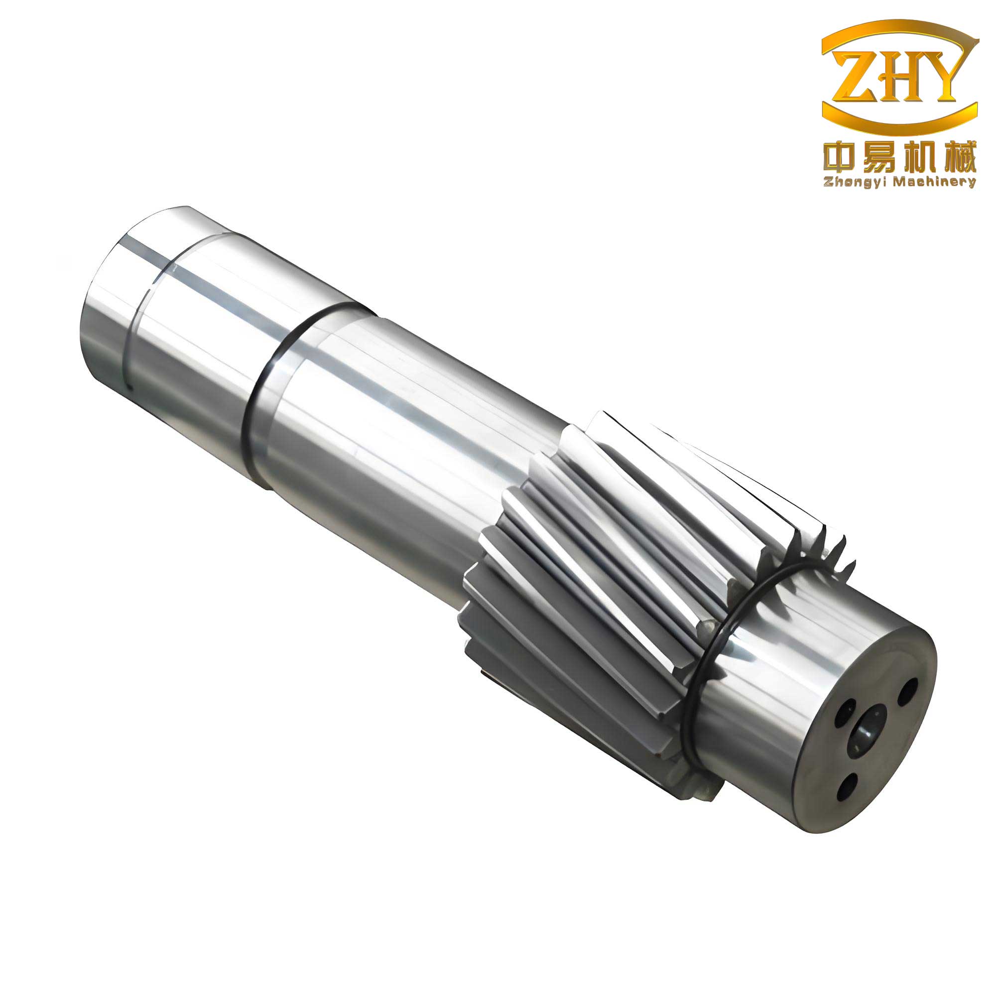
In assemblies involving gear shafts, a common site for fretting wear is the shoulder where a bearing inner ring is seated. This contact is often subjected to a combination of a static preload from an interference fit and dynamic loads from transmitted torque and system vibrations. The interference fit between the bearing and the gear shaft is essential for ensuring a solid connection to transmit torque. However, this very fit also governs the contact pressure and the minute relative displacements (slip amplitude) at the shoulder interface—two parameters critically controlling the onset and severity of fretting wear. This work employs a combined analytical and finite element analysis (FEA) approach to systematically investigate how the degree of interference fit in gear shafts influences the contact mechanics and the consequent fretting wear at the shaft shoulder.
Theoretical Foundation for Interference Fit in Gear Shafts
The assembly of a bearing onto a gear shaft can be mechanically idealized as the interference fit between two thick-walled cylinders. The required interference must satisfy both static torque transmission requirements and dynamic conditions when the gear shaft rotates at high speeds, where centrifugal forces can alter the contact pressure. The total minimum required interference, $\delta_{\text{min}}$, is therefore composed of a static component, $\delta_{s,\text{min}}$, and a dynamic component, $\delta_{d}$.
The static component ensures sufficient contact pressure to transmit the maximum operational torque without slip under stationary or low-speed conditions. Its minimum value is derived from thick-cylinder theory and force equilibrium:
$$
\delta_{s,\text{min}} = \frac{2(1-\nu^2) M_t}{\pi \mu E l d} \left( \frac{1+c_e^2}{1-c_e^2} + \frac{1+c_i^2}{1-c_i^2} \right)
$$
The dynamic component accounts for the reduction in contact pressure due to centrifugal expansion of the bearing inner ring at high rotational speeds. It is given by:
$$
\delta_{d} = \frac{\rho \omega^2 (1+\nu)(3-2\nu) (1 – c_e^2 c_i^2) d^3}{16 E c_e^2}
$$
where $M_t$ is the transmitted torque, $\mu$ is the coefficient of friction at the interface, $E$ is the Young’s modulus, $\nu$ is the Poisson’s ratio, $l$ is the effective contact length, $d$ is the nominal interface diameter, $\rho$ is the material density, and $\omega$ is the angular velocity. The ratios $c_e$ and $c_i$ are defined as $c_e = d / d_2$ and $c_i = d_1 / d$, with $d_2$ being the bearing inner ring’s outer diameter and $d_1$ being the inner diameter of the hollow gear shaft (or zero for a solid shaft).
The total minimum interference is thus:
$$
\delta_{\text{min}} = \delta_{s,\text{min}} + \delta_{d}
$$
For typical high-speed gear shafts, analysis shows that $\delta_{s,\text{min}}$ is often an order of magnitude larger than $\delta_{d}$, indicating that the static torque transmission requirement is the dominant design driver for the interference fit.
| Parameter | Symbol | Value | Unit |
|---|---|---|---|
| Interface Diameter | $d$ | 55 | mm |
| Shaft Inner Diameter | $d_1$ | 42 | mm |
| Bearing Inner Ring OD | $d_2$ | 77 | mm |
| Contact Length | $l$ | 51 | mm |
| Transmitted Torque | $M_t$ | 400 | N·m |
| Max. Rotational Speed | $n_{\text{max}}$ | 7500 | rpm |
| Young’s Modulus | $E$ | 210 | GPa |
| Poisson’s Ratio | $\nu$ | 0.3 | – |
| Coefficient of Friction | $\mu$ | 0.11 | – |
| Material Density | $\rho$ | 7850 | kg/m³ |
| Calculated $\delta_{s,\text{min}}$ | – | 24.43 | µm |
| Calculated $\delta_{d}$ | – | 0.38 | µm |
| Total $\delta_{\text{min}}$ | – | ~24.8 | µm |
Computational Framework: Finite Element Modeling and Wear Simulation
To analyze the local stress state and micro-slip at the shoulder of the gear shaft, a three-dimensional finite element model was developed using a commercial FEA software, ABAQUS. The model encompasses the gear shaft segment containing the shoulder and the bearing inner ring. The interaction at the interface between the bearing and the shaft (including the cylindrical fit and the shoulder face) is defined using a surface-to-surface contact algorithm with a penalty friction formulation. The classical Coulomb friction model is employed, where the critical shear stress $\tau_{\text{max}}$ at a contact point is proportional to the contact pressure $p$:
$$
\tau_{\text{max}} = \mu \cdot p
$$
The material for both components is modeled as linear elastic with properties defined in Table 1. A key challenge in fretting simulations is accurately capturing the high stress gradients at the edge of contact. Therefore, the mesh is heavily refined in the region of the shaft shoulder and the corresponding contact area on the bearing inner ring. Eight-node linear brick elements (C3D8I) with incompatible modes are used to improve bending behavior and contact accuracy.
The loading is applied in two steps: first, the interference fit is simulated using a “shrink fit” contact condition or by imposing a radial displacement; second, the operational torque is applied to the gear shaft while the bearing’s outer surface is constrained appropriately.
Fretting wear is primarily an adhesive-abrasive process in dry contacts. To estimate wear depth, the Archard wear model, a widely used phenomenological law, is adopted. The incremental wear depth $\Delta h$ at a point on the surface over a small sliding distance $\Delta s$ is given by:
$$
\Delta h = k \frac{p}{H} \Delta s
$$
where $k$ is the dimensionless wear coefficient, $p$ is the contact pressure, and $H$ is the hardness of the softer material. In a fretting cycle with a relative slip amplitude $S$, the wear per cycle can be approximated. For computational efficiency, the FEA results (contact pressure $p$ and slip amplitude $S$) from a steady-state cycle are extracted and post-processed using this law to map the comparative wear depth distribution across the shoulder face for different interference levels. This approach provides a qualitative and quantitative comparison of wear severity.
Results: Influence of Interference Magnitude on Contact Mechanics
The analysis was performed for a constant applied torque but with varying interference fit levels, ranging from near the minimum calculated value to significantly higher values. The primary outputs of interest are the contact pressure distribution on the shaft shoulder and the relative displacement (slip) amplitude between the bearing and shoulder surfaces.
Contact Pressure Distribution
The contact pressure on the shoulder face is highly non-uniform. It is minimum at the inner edge (close to the shaft fillet) and increases sharply towards the outer diameter. This gradient is due to the bending stiffness of the bearing ring and the localized nature of the contact. The key finding is that the magnitude of the contact pressure across the entire shoulder is strongly dependent on the interference fit.
| Interference Fit (µm) | 28 | 34 | 39 | 43 | 45 | 50 |
|---|---|---|---|---|---|---|
| Max. Contact Pressure (MPa) | 152.3 | 178.9 | 199.5 | 215.8 | 223.1 | 242.7 | % Increase from 28µm | 0% | 17.5% | 31.0% | 41.7% | 46.5% | 59.4% |
As illustrated in Table 2, increasing the interference from 28 µm to 50 µm raises the peak contact pressure by approximately 60%. A higher contact pressure increases the frictional shear stress required to cause slip but also intensifies the surface and sub-surface stress field, potentially accelerating surface fatigue and wear particle formation.
Relative Slip Amplitude
Under cyclic torsional loading, the shoulder and the bearing inner ring undergo elastic deformation. The mismatch in their local deformations results in a small relative tangential movement—the slip amplitude. This amplitude is not constant but varies radially across the contact patch. The FEA results reveal two critical trends concerning the radial ($S_r$) and axial ($S_a$) components of slip amplitude at the outermost point of the shoulder.
First, the axial slip amplitude remains relatively constant regardless of the interference change. Second, and more significantly, the radial slip amplitude increases substantially with increasing interference. This is because a tighter fit creates a stiffer connection, altering the load path and deformation mode of the bearing ring under torque.
| Interference Fit (µm) | 28 | 34 | 39 | 43 | 45 | 50 |
|---|---|---|---|---|---|---|
| Radial Slip, $S_r$ (µm) | 1.05 | 1.28 | 1.46 | 1.60 | 1.66 | 1.85 |
| Axial Slip, $S_a$ (µm) | 0.75 | 0.74 | 0.73 | 0.73 | 0.72 | 0.72 |
Integrated Wear Analysis and Discussion
Combining the results from the contact pressure and slip amplitude analyses allows for an assessment of fretting wear severity using the Archard wear model. The estimated wear depth per cycle, $h_c$, is proportional to the product of contact pressure $p$ and the total slip distance per cycle (approximately $4S$, considering the reciprocating motion). Therefore, a comparative wear index $W$ at a point can be defined as:
$$
W \propto p \cdot S
$$
where $S$ is the resultant slip amplitude. The calculated wear depth distribution across the shoulder height for different interferences is summarized in Table 4. The wear is normalized to the value at the 28µm interference for the outermost point.
| Shoulder Height (mm from inner edge) | Normalized Wear Depth (Relative to 28µm case at outer edge) | |||||
|---|---|---|---|---|---|---|
| Interference (µm) | 28 | 34 | 39 | 43 | 45 | 50 |
| 0.0 | 0.12 | 0.13 | 0.14 | 0.15 | 0.15 | 0.16 |
| 1.0 | 0.25 | 0.28 | 0.30 | 0.32 | 0.33 | 0.36 |
| 2.0 | 0.41 | 0.46 | 0.50 | 0.53 | 0.55 | 0.60 |
| 3.0 | 0.68 | 0.78 | 0.86 | 0.92 | 0.95 | 1.05 |
| 3.8 (Outer Edge) | 1.00 | 1.21 | 1.38 | 1.51 | 1.57 | 1.78 |
The data leads to several conclusive insights regarding gear shafts:
- Wear Gradient: Fretting wear on the shoulder of a gear shaft is not uniform. It increases monotonically from the inner to the outer edge, with the most severe wear occurring at the outer diameter. This aligns with the concentration of both contact pressure and slip amplitude in that region.
- Interference Dependence: The severity of fretting wear across the entire shoulder face is strongly amplified by an increase in the interference fit. For the outer edge, increasing interference from 28 µm to 50 µm is predicted to increase the wear rate by approximately 78%.
- Underlying Mechanism: This exacerbation of wear is driven by the combined effect of the interference fit on the two governing parameters of the Archard law. While a larger interference increases contact pressure $p$ (which can suppress gross slip but increases stress), it also significantly increases the radial slip amplitude $S_r$. The product $p \cdot S$, and thus the wear rate, increases substantially. The constant axial slip contributes less to this trend.
- Design Implication: There exists a critical trade-off. The interference fit in gear shafts must be above a minimum threshold ($\delta_{\text{min}}$) to prevent slippage under torque and to maintain structural integrity. However, exceeding this necessary value, while perhaps providing a larger safety factor against slip, can be detrimental as it promotes fretting wear at the shoulder. The optimal design aims for an interference value that is sufficient for torque transmission and dynamic stability but minimizes the product of contact pressure and micro-slip at the shoulder interface.
Conclusion
This investigation provides a detailed computational analysis of the fretting wear problem at the shoulder of power-transmitting gear shafts. The study establishes a clear causal link between the selected interference fit and the rate of surface degradation. Through analytical calculation and nonlinear finite element simulation, it was demonstrated that:
- The minimum required interference for gear shafts is predominantly determined by static torque transmission requirements, with dynamic centrifugal effects playing a minor role for typical operational speeds.
- The contact pressure on the shaft shoulder increases monotonically with increased interference, creating a more severe surface stress state.
- Contrary to perhaps an intuitive expectation, the relative micro-slip amplitude at the interface, particularly in the radial direction, also increases with greater interference, altering the local deformation mechanics.
- The synergistic increase of both contact pressure and slip amplitude with higher interference leads to a substantial increase in predicted fretting wear, especially at the vulnerable outer edge of the shoulder.
Therefore, the design of the interference fit for bearings on gear shafts should not be based solely on the criterion of torque transmission with a large safety margin. A comprehensive approach must consider fretting wear durability. Selecting an interference value that is “appropriate”—sufficiently above the calculated $\delta_{\text{min}}$ to account for manufacturing variances and ensure reliable performance, but not excessively high—can effectively mitigate fretting wear at the shaft shoulder, thereby enhancing the long-term reliability and service life of the entire power transmission system. Future work could integrate elastoplastic material models, third-body effects from wear debris, and experimental validation to further refine the wear prediction for critical gear shaft applications.