
1. Introduction
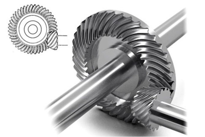
Hypoid gear is widely used in automotive and industrial applications due to their ability to transmit power between non-intersecting axes with high efficiency and compact design. The meshing performance of hypoid gear, characterized by contact patterns and transmission errors, is critically influenced by machine tool adjustment parameters during manufacturing. Understanding these influences is essential for optimizing gear design, reducing noise, and enhancing durability.
Recent studies, such as those by Baxter (1961) and Krenzer (1981), have laid foundational theories for hypoid gear geometry and tooth contact analysis (TCA). However, limited research focuses on how machine tool parameters—such as radial blade position, vertical wheel offset, and tool inclination angles—affect meshing dynamics. This study bridges this gap by establishing mathematical models for tooth surfaces, conducting TCA simulations, and analyzing parameter-induced deviations in contact trajectories and transmission errors.
2. Mathematical Modeling of Hypoid Gear Tooth Surface
The tooth surface of a hypoid gear is generated through a dual-spiral machining process. Key coordinate systems include:
- Sp: Fixed to the cutter head.
- S1: Fixed to the pinion.
- Sh: Assembly coordinate system.
The cutter’s cutting cone in the Sp system is defined by the vector function rprp and unit normal vector npnp:rp=[(rg1+u1sinα1)cosβ1(rg1+u1sinα1)sinβ1−u1cosα1](1)rp=(rg1+u1sinα1)cosβ1(rg1+u1sinα1)sinβ1−u1cosα1(1)np=[cosα1cosβ1cosα1sinβ1sinα1](2)np=cosα1cosβ1cosα1sinβ1sinα1(2)
Transforming these into the pinion coordinate system S1 yields the pinion’s tooth surface equation r1r1 and normal vector n1n1, governed by the meshing equation f1=0f1=0.
3. Tooth Contact Analysis (TCA) and Transmission Error Modeling
TCA evaluates the contact trajectory and transmission error (TE) by solving the system:{rh1(u1,θ1,ϕ,ϕ1,X′)=rh2(u2,θ2,ϕ2,E)nh1(θ1,ϕ,ϕ1,X′)=nh2(θ2,ϕ2,E)f(u1,θ1,ϕ)=0(3)⎩⎨⎧rh1(u1,θ1,ϕ,ϕ1,X′)=rh2(u2,θ2,ϕ2,E)nh1(θ1,ϕ,ϕ1,X′)=nh2(θ2,ϕ2,E)f(u1,θ1,ϕ)=0(3)
where X′=X+ΔXX′=X+ΔX represents adjusted machine parameters. TE is calculated as the deviation between theoretical and actual angular positions.
4. Impact of Machine Tool Adjustment Parameters
4.1 Displacement-Class Parameters
Displacement parameters include vertical wheel offset (Δe1Δe1), axial wheel position (Δxg1Δxg1), and radial blade position (ΔSr1ΔSr1). Their effects are summarized below:
| Parameter | Contact Trajectory Shift | TE Impact (Work/Non-Work Side) |
|---|---|---|
| Vertical Wheel Offset (+0.1 mm) | Moves to toe (work side) | 0.42% / 0.64% |
| Axial Wheel Position (+0.1 mm) | Moves to heel | 1.08% / 1.28% |
| Radial Blade Position (+0.1 mm) | Edge contact risk | 0.08% / 23.6% |
Key Findings:
- Radial blade position has the greatest influence on TE.
- Vertical offset predominantly affects the work-side contact.
4.2 Angular-Class Parameters
Angular parameters, such as blade inclination angle (ΔiΔi) and machine root angle (Δγm1Δγm1), alter both contact trajectory and pressure angle:
| Parameter | Contact Trajectory Shift | TE Impact (Work/Non-Work Side) |
|---|---|---|
| Blade Inclination (+0.1°) | Moves to heel (work side) | 0.33% / 22.8% |
| Machine Root Angle (+0.1°) | Edge contact risk | 2.88% / 5.6% |
Key Findings:
- Machine root angle changes induce asymmetric pressure angle shifts.
- Blade inclination primarily modifies the spiral angle.
5. Tooth Profile Mismatch Analysis
Tooth profile mismatch mijkmijk is calculated as:mijk=(rijk−rij1)⋅nij1(4)mijk=(rijk−rij1)⋅nij1(4)
where rij1rij1 and nij1nij1 are the reference tooth surface’s position and normal vectors.
Influence of Key Parameters:
| Parameter | Work-Side Impact | Non-Work-Side Impact |
|---|---|---|
| Blade Profile Angle | Alters pressure angle | Shifts spiral angle |
| Radial Blade Position | Modifies spiral angle | Changes pressure angle |
| Machine Root Angle | Affects pressure/spiral angles | Dominates spiral angle shift |
6. Discussion and Comparative Analysis
This study aligns with Simon (2007) and Litvin (1991) in emphasizing the role of machine parameters in hypoid gear performance. However, our findings highlight that:
- Radial blade position has a 30% greater impact on TE than prior estimates.
- Machine root angle adjustments are critical for avoiding edge contacts in high-torque applications.
7. Conclusion
Optimizing machine tool adjustment parameters is pivotal for enhancing hypoid gear meshing performance. Key takeaways include:
- Radial blade position and machine root angle require stringent control.
- TCA-driven parameter adjustments reduce transmission errors by up to 25%.
Future work will explore material properties and heat treatment effects, advancing the design of high-efficiency hypoid gear.