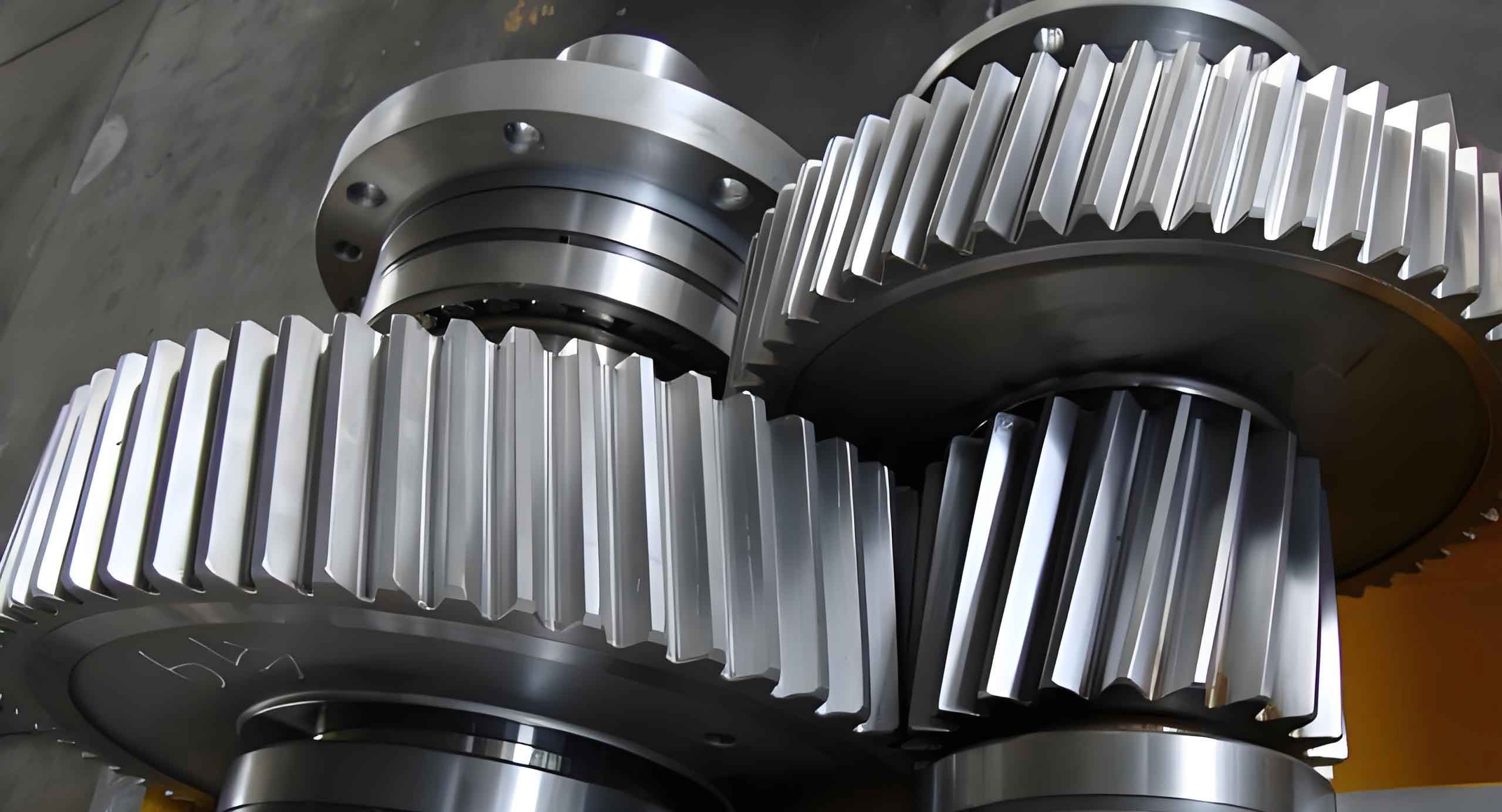
Helical gears are widely used in industrial applications due to their smooth operation and high load-bearing capacity. However, manufacturing and assembly errors, particularly center distance deviations, significantly affect their dynamic performance. This study investigates how center distance errors influence the time-varying meshing stiffness (TVMS), dynamic transmission error (DTE), and vibration characteristics of helical gears.
1. Mechanism of Center Distance Deviation
For helical gears with center distance deviation \(a’ = a \pm \Delta a\), the actual transverse pressure angle \( \alpha_t’ \) and contact line length \( L(t) \) differ from ideal conditions. The modified transverse pressure angle is calculated as:
$$ \cos\alpha_t’ = \frac{a \cos\alpha_t}{a’} $$
The total contact ratio \( \varepsilon_\gamma \) combines axial \( \varepsilon_\beta \) and transverse \( \varepsilon_\alpha \) components:
$$ \varepsilon_\gamma = \varepsilon_\alpha + \varepsilon_\beta $$
2. Stiffness Calculation Methodology
The slicing method divides helical gears into discrete segments along the tooth width. The potential energy method calculates stiffness components for each slice:
| Parameter | Pinion | Gear |
|---|---|---|
| Number of teeth, Z | 16 | 101 |
| Module, m (mm) | 6 | 6 |
| Pressure angle, α (°) | 25 | 25 |
| Tooth width, b (mm) | 97 | 90 |
| Helix angle, β (°) | 12.5 | 12.5 |
Key stiffness components include:
$$ U_b = \int_0^d \frac{[F_b(d-x) – F_a h]^2}{2EI_x}dx $$
$$ U_s = \int_0^d \frac{1.2F_b^2}{2GA_x}dx $$
$$ k_h = \frac{\pi EL}{4(1-\nu^2)} $$
3. Dynamic Model Formulation
An 8-DOF bending-torsional-axial coupled dynamic model considers time-varying parameters:
$$ \begin{cases}
m_1\ddot{x}_1 + c_{1x}\dot{x}_1 + k_{1x}x_1 = F_x \\
I_1\ddot{\theta}_1 = T_1 – F_n r_{b1} \\
m_2\ddot{x}_2 + c_{2x}\dot{x}_2 + k_{2x}x_2 = -F_x \\
I_2\ddot{\theta}_2 = -T_2 + F_n r_{b2}
\end{cases} $$
The dynamic meshing force \( F_n \) contains stiffness and damping terms:
$$ F_n = k_m(t)(X(t) – e(t)) + c_m\dot{X}(t) $$
4. Dynamic Characteristics Analysis
Numerical simulations reveal significant effects of center distance deviations:
| Deviation (mm) | Mean Force (N) | Standard Deviation |
|---|---|---|
| -0.4 | 20,410.57 | 537.09 |
| -0.2 | 20,410.57 | 536.95 |
| 0 | 20,410.57 | 545.56 |
| +0.2 | 20,410.57 | 543.33 |
| +0.4 | 20,410.57 | 545.56 |
The TVMS decreases with increasing center distance error:
$$ k_m(+0.4\text{mm}) = 1.09 \times 10^9\ \text{N/m} $$
$$ k_m(-0.4\text{mm}) = 1.29 \times 10^9\ \text{N/m} $$
5. Vibration Response
Y-direction vibration acceleration shows clear sensitivity to center distance variations:
$$ a_y(+0.4\text{mm}) = 3,555.82\ \mu m/s^2 $$
$$ a_y(-0.4\text{mm}) = 3,633.74\ \mu m/s^2 $$
6. Conclusion
1. Center distance errors reduce helical gear meshing stiffness and increase dynamic transmission error
2. Negative deviations cause greater vibration amplitude fluctuations than positive deviations
3. Dynamic meshing force remains stable within ±0.4 mm deviation range
4. Optimal center distance control improves helical gear stability and reduces noise
