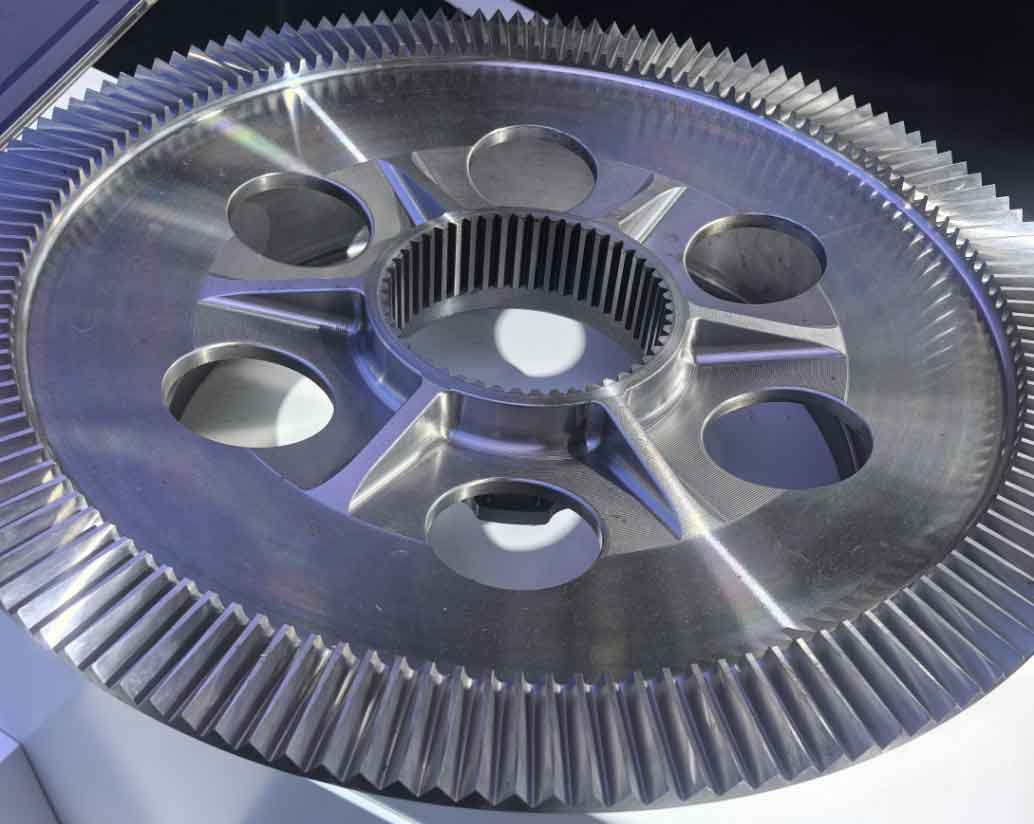
Power skiving revolutionizes gear machining by enabling high-speed processing of internal/external and spur/helical gears with reduced cycle times. However, accurately predicting cutting forces—essential for optimizing tool life and preventing vibration—remains computationally intensive due to complex kinematics. This work introduces a dexel-based discrete modeling approach for efficient and precise cutting force simulation in cylindrical gear machining.
1. Kinematic Model of Power Skiving
Power skiving involves crossed axes (Σ) between tool and workpiece. The tool rotates at angular velocity \( \omega_c \) while translating axially at feed rate \( v_f \). For helical gears, the tool rotation is governed by:
$$ \omega_c = \frac{N_g}{N_c} \omega_g + \frac{v_f \tan\beta_g}{r_{pc}} $$
where \( N_g \) and \( N_c \) are gear and tool teeth counts, \( \beta_g \) is the gear helix angle, and \( r_{pc} \) is the tool pitch radius. The transformation matrix \( M^g_c \) from workpiece coordinate system (WCS) to tool coordinate system (TCS) combines rotations and translations:
$$ M^g_c = R_{z,-\theta_g} T_{g→c} T_{c→rac} R_{y,\psi} T_{rac→c} R_{z,\theta_c} $$
Cutting velocity \( \mathbf{v_c} \) at any tool point \( P \) is critical for local force calculations:
$$ \mathbf{v_c} = \boldsymbol{\omega_c} \times \mathbf{r_{P/c}} – \boldsymbol{\omega_g} \times \mathbf{r_{P/g}} + \mathbf{v_f} $$
2. Dexel-Based Cutting Force Prediction
Our method leverages dexel discrete geometry to model material removal efficiently.
2.1 Undeformed Chip Geometry Extraction
The workpiece is represented as parallel dexels (line segments). Boolean subtraction of the tool’s swept volume at discrete timesteps updates the dexel model. 3D chip boundaries are reconstructed by connecting dexel endpoints in xy, xz, and yz planes. Alpha-shape algorithm (\( \alpha = \sqrt{3}d \), where \( d \) is dexel resolution) processes the point cloud to derive 2D chip sections.

2.2 Oblique Cutting Force Calculation
Tool edges are discretized into nodes. For each node, effective rake angle \( \alpha_n \) and inclination \( i \) are computed using local edge geometry and \( \mathbf{v_c} \). Force components in tangential (t), feed (f), and radial (r) directions are:
$$ F_t = K_{tc} a + K_{te} b, \quad F_f = K_{fc} a + K_{fe} b, \quad F_r = K_{rc} a + K_{re} b $$
where \( a \) is uncut chip area, \( b \) is edge length, and \( K \) coefficients are material-specific (e.g., AISI4340 steel). Forces are vector-summed in TCS.
2.3 Partial Workpiece Superposition for Efficiency
To accelerate simulation, forces are computed for one tooth gap over one gear rotation period \( t_g = 60/(2\pi\omega_g) \). Linear interpolation maps forces to subsequent gaps. Total force is the superposition of all gaps:
$$ \mathbf{F_{total}} = \sum_{k=1}^{N_g} \mathbf{F_k}(t – (k-1)t_g) $$
This reduces computational load by \( \sim N_g \)-fold while preserving accuracy.
3. Experimental Validation
Tests used a DMG NT5400DCG machine, AlCrN-coated HSS tool, and AISI4340 gear blank. Cutting forces were measured via a SPIKE wireless toolholder (2.5 kHz sampling). Parameters:
| Parameter | Gear | Tool |
|---|---|---|
| Module (mm) | 3.9 | 3.9 |
| Pressure Angle (°) | 20 | 20 |
| Tip Diameter (mm) | 120.9 | 106.38 |
| Face Width (mm) | 22.75 | 5 |
| Helix Angle (°) | 0 | 20 |
| Parameter | Value |
|---|---|
| Crossed-Axis Angle Σ (°) | 20 |
| Tool Tilt ψ (°) | 0 |
| Tool Speed (rpm) | 667 |
| Workpiece Speed (rpm) | 841 |
| Cutting Speed (m/min) | 95.8 |
| Axial Feed (mm/rev) | 0.25 |
Predicted vs. measured forces showed close alignment. RMS errors were:
| Method | Fx RMS Error (N) | Fy RMS Error (N) | Fz RMS Error (N) |
|---|---|---|---|
| CAD-Based Model | 25 | 27 | 64 |
| Proposed Method | 23 | 23 | 60 |
Normalized RMS errors decreased by 9.7% on average, with a 7 N mean error reduction. The method achieved high accuracy without coefficient recalibration—critical for adaptive gear machining.
4. Conclusion
This dexel-based approach enables efficient and precise cutting force prediction in cylindrical gear machining. Key advantages:
- Computational efficiency improved via partial-workpiece superposition.
- Accurate 3D chip geometry extraction using dexel alpha-shaping.
- 9.7% lower RMS errors vs. CAD-based methods, enhancing tool life prediction.
Future work will integrate vibration dynamics to further optimize high-speed gear machining processes.
