
In the manufacturing of electric tools, the precision of motor rotor shaft gears after heat treatment is critical, as it directly impacts product performance and lifespan. These gears are typically slender cylindrical helical gears with complex geometries, and they undergo high-frequency induction heat treatment. However, heat treatment defects such as dimensional distortions and geometric inaccuracies are common challenges that affect final quality. This article explores our systematic approach to minimizing these heat treatment defects through controlled processes and compensatory measures, based on extensive testing and analysis.
The rotor shaft gears in question have specifications including a normal module (mn) ranging from 0.7 to 1.25 mm, major diameters between φ6.2 and 14 mm, and effective lengths from 8.5 to 20 mm. They are integrated with bearing and fan sections, all subjected to high-frequency heat treatment. Historically, quality control focused only on hardness checks and visual inspections, often overlooking geometric deviations. These heat treatment defects arise from rapid heating (exceeding 500°C/s) and cooling (over 300°C/s), which induce non-uniform thermal stresses and phase transformation stresses due to varying cross-sectional areas. This leads to significant distortions, particularly in regions with abrupt shape changes, such as between the gear and bearing sections. To address these issues, we implemented a comprehensive study using advanced gear testing equipment to quantify and mitigate heat treatment defects.
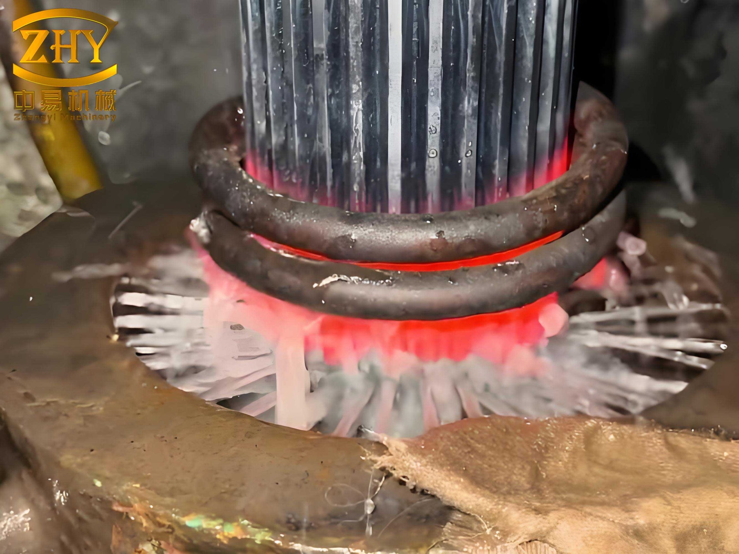
Our investigation began with measuring geometric parameters before and after heat treatment for a sample batch of rotor shaft gears from a 6C electric drill model. Key parameters included: normal module mn = 0.7, number of teeth = 26, pressure angle α = 20°, helix angle β = 20° (right-hand), and specified tolerances for runout, profile, and lead errors. The heat treatment defects were primarily evaluated through changes in gear accuracy metrics. Table 1 summarizes the measurement results for 20 samples, highlighting deviations in radial runout (ΔFr), base tangent length variation (ΔFw), profile error (Δfr), and lead error (ΔFβ).
| Sample ID | ΔFr (Before) | ΔFr (After) | ΔFw (Before) | ΔFw (After) | Wk Deviation (Before) | Wk Deviation (After) | Δfr (Before) | Δfr (After) | ΔFβ (Before) | ΔFβ (After) |
|---|---|---|---|---|---|---|---|---|---|---|
| 1 | 10 | 12 | 2 | 2 | +12 | +11 | 7 | 14 | 6 | 20 |
| 2 | 9 | 6 | 3 | 3 | +13 | +13 | 8 | 14 | 10 | 27 |
| 3 | 7 | 4 | 4 | 3 | +10 | +11 | 13 | 20 | 8 | 29 |
| 4 | 3 | 9 | 4 | 6 | +12 | +10 | 11 | 10 | 9 | 30 |
| 5 | 15 | 16 | 3 | 3 | +13 | +13 | 11 | 12 | 7 | 24 |
| 6 | 3 | 8 | 3 | 3 | +10 | +11 | 11 | 17 | 5 | 29 |
| 7 | 7 | 10 | 3 | 3 | +15 | +13 | 5 | 12 | 10 | 32 |
| 8 | 6 | 12 | 2 | 2 | +15 | +13 | 5 | 14 | 9 | 26 |
| 9 | 6 | 5 | 4 | 5 | +12 | +8 | 10 | 16 | 11 | 28 |
| 10 | 5 | 9 | 4 | 3 | +17 | +9 | 7 | 12 | 12 | 34 |
| 11 | 19 | 20 | 3 | 3 | +13 | +10 | 12 | 15 | 10 | 29 |
| 12 | 16 | 26 | 3 | 3 | +13 | +9 | 14 | 17 | 11 | 26 |
| 13 | 11 | 12 | 2 | 3 | +14 | +10 | 8 | 11 | 10 | 32 |
| 14 | 4 | 8 | 2 | 2 | +14 | +10 | 9 | 13 | 10 | 27 |
| 15 | 9 | 7 | 4 | 3 | +15 | +11 | 6 | 9 | 8 | 29 |
| 16 | 9 | 10 | 3 | 3 | +16 | +10 | 6 | 11 | 12 | 28 |
| 17 | 6 | 18 | 2 | 4 | +15 | +12 | 9 | 14 | 9 | 24 |
| 18 | 4 | 8 | 3 | 2 | +17 | +13 | 14 | 17 | 10 | 26 |
| 19 | 6 | 4 | 3 | 2 | +15 | +20 | 10 | 20 | 10 | 34 |
| 20 | 2 | 8 | 3 | 3 | +17 | +13 | 9 | 13 | 7 | 27 |
Analysis revealed that while radial runout, base tangent length, and profile errors remained within tolerances, lead error (ΔFβ) increased significantly after heat treatment, exceeding design requirements. This indicated a systematic heat treatment defect related to helix angle distortion. The lead error curves showed a consistent shift toward smaller helix angles, with an average deviation calculated as Δβ = -9 arcminutes (i.e., -0.15°). This pattern suggested that compensating for this distortion during gear cutting could mitigate the heat treatment defects. The relationship can be expressed as:
$$ \beta_{\text{corrected}} = \beta_{\text{design}} + \Delta \beta $$
where βdesign is the nominal helix angle (20°), and Δβ is the corrective angle derived from empirical data. For the 6C drill gears, Δβ = +9 arcminutes was applied to pre-heat treatment gear cutting.
To implement this correction effectively, we optimized the high-frequency heat treatment process using a dedicated automatic quenching machine (FH-S30ML) with a frequency of 300 kHz. The goal was to stabilize parameters and minimize variability in heat treatment defects. Key electrical and temporal parameters were established through iterative testing, focusing on achieving desired hardness and microstructure while controlling distortions. The heat treatment defects are influenced by heating and cooling rates, which we characterized using hardness-time curves. For instance, the optimal quenching time (tq) was determined from hardness versus heating time curves, where the intersection point of curves represents the best balance. Similarly, tempering time (tt) was optimized to reduce residual stresses. These relationships can be modeled as:
$$ H(t) = H_0 + k \cdot \ln(t) \quad \text{(for quenching)} $$
where H(t) is hardness at time t, H0 is base hardness, and k is a material constant. For the 6C drill gears, the optimized parameters are summarized in Table 2.
| Process Step | Anode Voltage Ep (kV) | Anode Current Ip (A) | Grid Current Ig (A) | Time (s) |
|---|---|---|---|---|
| Quenching Heating | 9.3–9.5 | 3.1–3.2 | 0.40–0.41 | 1.6 |
| Tempering Heating | 1.8–2.0 | 0.6–0.8 | 0.04–0.06 | 4.0 |
Cooling was performed using a K-140 aqueous solution at 4–5% concentration, 22–25°C temperature, and 0.15–0.18 MPa spray pressure. The sequence included quenching spray (1.5 s), air cooling (1.8 s), tempering spray (1.5 s), and delays. This controlled approach reduced heat treatment defects by ensuring uniform transformation. Post-treatment hardness and microstructure met specifications, as shown in Table 3.
| Sample | Gear Section Hardness (HRC) | Bearing Section Hardness (HRC) | Fan Section Hardness (HRC) | Microstructure |
|---|---|---|---|---|
| 1 | 50.5 | 51.0 | 51.0 | Fine tempered martensite |
| 2 | 50.5 | 51.0 | 52.0 | Fine tempered martensite |
| 3 | 50.0 | 50.0 | 51.0 | Fine tempered martensite |
| 4 | 50.5 | 51.0 | 52.0 | Fine tempered martensite |
| 5 | 50.5 | 51.0 | 51.0 | Fine tempered martensite |
With the helix angle correction applied, we re-evaluated lead errors after heat treatment. The results, presented in Table 4, demonstrate a significant reduction in heat treatment defects, with ΔFβ values falling within acceptable limits.
| Sample ID | ΔFβ (Before Correction) | ΔFβ (After Correction & Heat Treatment) |
|---|---|---|
| 1 | 30 | 8 |
| 2 | 27 | 7 |
| 3 | 33 | 9 |
| 4 | 27 | 6 |
| 5 | 27 | 7 |
| 6 | 30 | 5 |
| 7 | 27 | 10 |
| 8 | 28 | 11 |
| 9 | 34 | 8 |
| 10 | 23 | 6 |
| 11 | 21 | 9 |
| 12 | 31 | 8 |
| 13 | 31 | 7 |
| 14 | 24 | 10 |
| 15 | 30 | 9 |
| 16 | 30 | 6 |
| 17 | 32 | 8 |
| 18 | 28 | 10 |
| 19 | 36 | 7 |
| 20 | 27 | 5 |
The success of this method hinges on stable material properties and repeatable heat treatment processes. Material inconsistencies, such as variations in chemical composition, can exacerbate heat treatment defects by affecting hardenability and transformation stresses. To address this, we introduced a preparatory heat treatment—quenching and tempering (tempering)—after rough machining. This homogenizes the microstructure into fine sorbitic grains, reduces gradient stresses, and stabilizes subsequent distortions. The benefits can be quantified using a stress reduction factor ξ:
$$ \xi = \frac{\sigma_{\text{without prep}} – \sigma_{\text{with prep}}}{\sigma_{\text{without prep}}} $$
where σ represents residual stress. For our gears, ξ typically ranges from 0.2 to 0.3, indicating a 20-30% reduction in stress-related heat treatment defects.
We applied this integrated approach to other products, such as a 13B electric drill rotor shaft made from 40CrMnMoA steel. The preparatory heat treatment involved tempering to HB 211-240, followed by optimized high-frequency parameters listed in Table 5. The corrective helix angle offset was approximately 13 arcminutes, further validating the generality of our method for mitigating heat treatment defects.
| Process Step | Anode Voltage Ep (kV) | Anode Current Ip (A) | Grid Current Ig (A) | Time (s) |
|---|---|---|---|---|
| Quenching Heating | 9.3–9.6 | 3.2–3.3 | 0.35–0.40 | 2.3 |
| Tempering Heating | 2.0 | 0.7–0.8 | 0.03–0.05 | 5.0 |
Cooling conditions were similar: K-140 solution at 4-5% concentration, 23-25°C, 0.18 MPa pressure, and spray time of 2.5 s. Post-treatment hardness and microstructure met all specifications, with minimal geometric deviations. This demonstrates that proactive compensation and process control are effective against heat treatment defects.
In summary, achieving high precision in cylindrical helical gears after heat treatment requires a multifaceted strategy. Key elements include: rigorous material inspection to minimize inherent variability; implementing preparatory heat treatment to enhance uniformity; utilizing advanced measurement tools for continuous monitoring; employing stable, adjustable heat treatment equipment with optimized parameters; and fostering cross-departmental collaboration for consistent execution. By addressing these factors, we can significantly reduce heat treatment defects and ensure gears meet geometric tolerances without costly post-treatment corrections. The helix angle compensation method, combined with optimized heat treatment cycles, provides a reliable framework for managing distortions. Future work may involve predictive modeling using finite element analysis to further refine these approaches and expand applicability to other gear types.
Throughout this study, we have emphasized that heat treatment defects are not inevitable but can be controlled through systematic analysis and corrective actions. The integration of compensatory manufacturing steps with precise thermal processing enables the production of high-quality gears that satisfy stringent performance criteria, ultimately enhancing product reliability and longevity in electric tool applications.