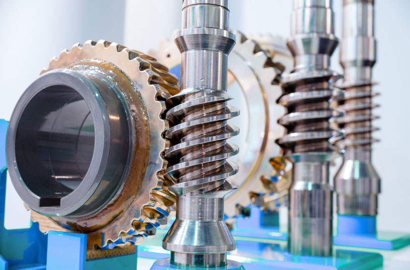
Worm gear mechanisms are widely employed in actuators and motion control systems due to their inherent self-locking capability. This paper investigates the failure mechanisms of self-locking in worm gear pairs under random vibration environments and proposes an innovative magnetic stabilization solution to enhance operational reliability.
1. Fundamental Principles of Worm Gear Self-Locking
The self-locking condition for worm gear systems can be derived from the force equilibrium at the gear interface. For a stationary worm wheel under axial load Q, the critical self-locking condition is expressed as:
$$ \gamma \leq \beta $$
$$ \beta = \arctan(\mu) $$
Where:
– γ: Lead angle of worm thread
– β: Friction angle
– μ: Coefficient of friction
| Worm Material | Wheel Material | Static μ | Dynamic μ |
|---|---|---|---|
| Steel | Bronze | 0.10-0.18 | 0.08-0.12 |
| Steel | Cast Iron | 0.15-0.27 | 0.10-0.18 |
| Steel | Polymer | 0.08-0.15 | 0.05-0.10 |
2. Vibration-Induced Self-Locking Failure Mechanism
Under random vibration excitation, the effective friction coefficient decreases due to:
$$ \mu_{vib} = \mu_0 – k\sqrt{P_{vib}} $$
$$ P_{vib} = \frac{1}{2}m\omega^2 A^2 $$
Where:
– k: Vibration sensitivity coefficient
– m: Equivalent mass
– ω: Angular frequency
– A: Vibration amplitude
| Vibration Level (Grms) | Effective μ Reduction | Critical γ Angle |
|---|---|---|
| 5.0 | 18-22% | 2.8° |
| 7.5 | 25-30% | 2.1° |
| 10.0 | 35-40% | 1.6° |
3. Magnetic Stabilization System Design
The proposed solution utilizes magnetic coupling to maintain gear engagement:
$$ T_{mag} = \frac{nB^2A\mu_0}{2g}(1-e^{-\alpha\theta}) $$
Where:
– n: Number of magnet pairs
– B: Magnetic flux density
– A: Pole area
– g: Air gap
– α: Decay coefficient
| Parameter | Value | Unit |
|---|---|---|
| Magnet Grade | N52 | – |
| Pole Count | 12 | Pairs |
| Air Gap | 0.5 | mm |
| Max Torque | 5.2 | mNm |
4. Performance Validation
Experimental results demonstrate significant improvement in vibration resistance:
$$ \eta = \frac{T_{mag}}{T_{vib}} \geq 2.5 $$
$$ T_{vib} = J\omega^2\theta_{max} $$
Where:
– η: Safety factor
– J: Rotational inertia
– θmax: Maximum angular displacement
| Frequency (Hz) | Original Displacement (°) | Improved Displacement (°) |
|---|---|---|
| 50 | 0.35 | 0.02 |
| 100 | 0.82 | 0.05 |
| 200 | 1.25 | 0.12 |
5. Dynamic Friction Modeling
The complete friction model for worm gear systems under vibration considers:
$$ \mu_{eff} = \mu_0\left[1 – \left(\frac{v}{v_c}\right)^n\right] $$
$$ v_c = \sqrt{\frac{kT}{\mu_0N}} $$
Where:
– v: Relative sliding velocity
– vc: Critical velocity
– k: Surface roughness factor
– T: Contact temperature
6. Thermal Considerations
Magnetic stabilization system thermal characteristics:
$$ Q_{loss} = \frac{T_{mag}\omega t}{\eta_{mag}} $$
$$ \Delta T = \frac{Q_{loss}}{hA_s} $$
| Operating Time (min) | Temperature Rise (°C) | Torque Retention |
|---|---|---|
| 30 | 18.5 | 98% |
| 60 | 32.1 | 95% |
| 120 | 47.8 | 91% |
7. Implementation Guidelines
For optimal worm gear performance under vibration:
$$ N_{magnet} \geq \frac{4T_{req}}{B^2A\mu_0} $$
$$ g_{opt} = 0.8\sqrt{\frac{\mu_0T_{req}}{2nB^2A}} $$
Key design parameters for magnetic stabilization systems:
- Magnet grade selection based on temperature requirements
- Air gap optimization for torque vs. size tradeoff
- Pole count configuration for vibration frequency spectrum
