
The manufacturing of large-scale, high-precision components, such as massive cast steel gear rings for mills, cement kilns, and power generation equipment, presents formidable challenges. The process of gear hobbing these components, which can exceed 7 meters in diameter and 40 tons in weight, demands extreme stability from the machine tool. A critical vulnerability in large high-speed CNC gear hobbing machines is the auxiliary rotary worktable and its support system. During the gear hobbing of such heavy parts, significant and fluctuating radial and axial loads, coupled with intense shock forces during tool entry and exit, frequently lead to catastrophic failures. This article details a systematic engineering analysis and redesign initiative aimed at resolving chronic failures—specifically bearing fracture and guideway wear—in the support system of a large-scale CNC gear hobbing machine, thereby ensuring unparalleled process stability for high-precision manufacturing.
1. The Critical Role of Worktable Stability in High-Performance Gear Hobbing
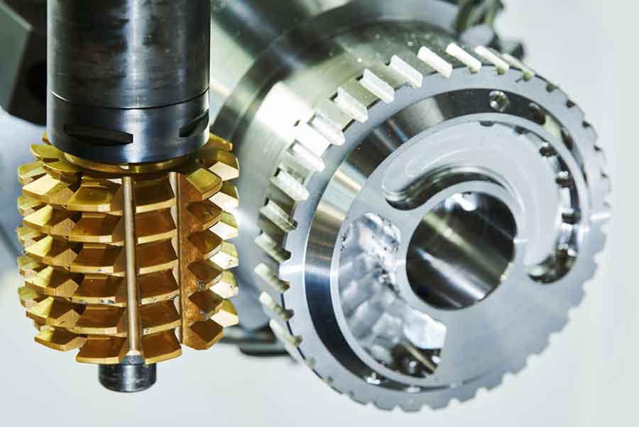
In modern gear hobbing, achieving high productivity requires high cutting speeds and feed rates. For large components, this is only feasible if the worktable—the platform supporting the massive workpiece—maintains exceptional rotational accuracy and rigidity under heavy and dynamic loads. Any instability, such as sudden deflection or loss of concentricity, translates directly into geometric errors on the gear teeth, including profile deviations, pitch errors, and surface defects like chatter marks or “gnawing” (see the phenomenon described in the provided material). The auxiliary worktable, necessary for oversized parts, becomes a single point of failure. Its support system, typically consisting of multiple bearing assemblies, must bear not only the static weight of the worktable, fixtures, and workpiece (Wtotal) but also dynamic cutting forces (Fcut) and impact shocks (Fshock). The total radial load (R) on a support can be approximated as:
$$ R = \frac{W_{total} \cdot g}{n} + k \cdot F_{cut} + \delta \cdot F_{shock} $$
where n is the number of supports, g is gravity, and k & δ are dynamic load factors often >1. The original support system’s inability to manage this complex load regime was the root cause of the frequent downtime, quality issues, and high maintenance costs.
2. In-Depth Failure Analysis of the Original Support System
The original configuration utilized eight support points, each equipped with a standard spherical roller bearing (e.g., model 21319-E1-TVPB). While suitable for pure radial loads in many applications, this design proved inadequate for the severe conditions of large-diameter gear hobbing. A multi-faceted failure analysis was conducted.
2.1 Bearing Fracture: A Consequence of Combined Stresses
The spherical roller bearing’s fracture was not due to a single cause but a combination of overloads for which it was not designed.
- Radial Overload: The static load alone per bearing was substantial. For a total mass (m) of 102,000 kg and 8 supports, the basic radial static load per bearing is:
$$ R_{static} = \frac{m \cdot g}{n} = \frac{102,000 \times 9.81}{8} \approx 125 \text{ kN} $$
Adding dynamic cutting forces, especially near the hob head, could easily push loads beyond the bearing’s static load rating (C0r). - Impact Loading: The intermittent nature of gear hobbing, with the hob engaging and disengaging the workpiece, generates significant shock impulses. These transient forces far exceed the average cutting force, creating cyclic stress peaks that promote fatigue crack initiation in the bearing rings.
- Torsional and Axial Loads: A critical oversight was the presence of parasitic loads. As the massive worktable rotates, inertial forces and machining reaction forces induce a twisting moment (Mtorsion) about the vertical axis. Furthermore, imperfect alignment or thermal effects can induce axial forces (Faxial). The spherical roller bearing, while accommodating minor misalignment, is not designed to sustain substantial continuous torsional moments or axial loads, leading to stress concentrations at the roller-end/flange interface and premature ring fracture.
The original bearing’s static load rating was 430 kN. Under the complex loading scenario, the effective combined load likely approached or exceeded this limit during shock events.
2.2 Guideway Wear: A Secondary Consequence
The severe wear on the cast steel guideway (hardness: 350-400 HBW) was a direct result of the primary bearing failure. Once a bearing outer ring cracked, the fractured surface acted as a cutting tool, catastrophically abrading the softer guideway material. Furthermore, inadequate surface hardness and potential lubrication issues accelerated wear even under normal conditions. The guideway’s monolithic design with the worktable meant that any repair required machining the entire structure, leading to material loss and eventual scrapping of the costly component.
| Failure Mode | Observed Symptom | Root Cause | Consequence |
|---|---|---|---|
| Bearing Fracture | Cracked outer ring, frequent replacement | Combined radial overload, impact shocks, and unaccounted torsional/axial loads. | Unplanned downtime, loss of worktable support, risk of catastrophic gear damage. |
| Guideway Wear | Deep scoring and material loss on rail surface | 1. Abrasion from fractured bearing pieces. 2. Insufficient surface hardness. 3. Monolithic, non-replaceable design. |
Loss of worktable geometric accuracy (runout), costly and finite repairability. |
| System Instability | Worktable vibration, poor gear finish (“gnawing”) | Sudden loss of support stiffness due to bearing failure and increased clearance from guideway wear. | Production of non-conforming parts, reduced process capability. |
3. A Systematic Redesign and Improvement Strategy
The improvement strategy targeted each root cause with a synergistic redesign of both the bearing support and the guideway.
3.1 Upgrading the Bearing: Selecting a Heavy-Duty Support Roller
The core of the solution was replacing the standard spherical roller bearings with specialized Heavy-Duty Support Roller Bearings (e.g., NNTR series). This choice was driven by a fundamental load capacity and functionality analysis.
- Enhanced Load Capacity: The NNTR bearing is a full-complement cylindrical roller design with a thick, hardened outer ring that acts directly as the rolling surface. Its static load rating was significantly higher.
- Combined Load Capability: Its internal geometry, with loose guide flanges on the inner ring, allows the outer ring to tilt slightly relative to the inner ring. This enables the bearing to withstand substantial tilting moments and associated axial components, directly addressing the torsional load issue present in gear hobbing.
- Increased Contact Area: The bearing width was increased from 45mm to 100mm, reducing contact pressure (σcontact) for a given radial load (R):
$$ \sigma_{contact} \propto \frac{R}{b \cdot l} $$
where b is the width and l is the effective contact length. This reduced stress directly mitigates fatigue and wear.
| Parameter | Original Bearing (e.g., 21319-E1-TVPB) | New Bearing (e.g., NNTR90x220x100.2ZL) | Improvement |
|---|---|---|---|
| Type | Spherical Roller Bearing | Heavy-Duty Support Roller Bearing | Specialized for track/rail guidance |
| Outer Ring | Standard thickness, spherical raceway | Very thick, cylindrical/radially crowned raceway | Higher bending stiffness, acts as roller |
| Static Load Rating (C0) | ~430 kN | ~750 kN | +74.4% |
| Width | 45 mm | 100 mm | +122% |
| Key Capability | High radial load, accommodates misalignment | Very high radial load, withstands tilting moments & axial forces | Directly addresses torsional loads in gear hobbing |
3.2 Redesigning the Support Assembly
A new housing (bearing托架) was designed to integrate the NNTR bearing and provide additional functionality:
- Height Adjustment Mechanism: A precision ground adjustment shim was incorporated at the base. This allows for fine-tuning of the bearing height (Hbearing) to ensure all eight supports are co-planar, guaranteeing uniform load distribution and a precise gap (δgap ≈ 0.02 mm) between the bearing and guideway. A dedicated checking fixture with a dial indicator was used to set this height accurately across all supports, minimizing preload and impact forces during rotation.
- Enhanced Sealing and Lubrication: A near-fully enclosed design with scrapers was implemented to prevent abrasive metal chips from the gear hobbing process from entering the bearing. A 45-degree angled grease nipple was added for easy, manual relubrication to maintain an anti-wear film on the guideway.
3.3 Revolutionizing the Guideway: Replaceability and Extreme Hardness
The guideway was re-engineered as a separate, replaceable component.
- Modular Design: The guideway was split into multiple segments made of 45 steel, bolted onto the main worktable body. This allows for individual replacement if damaged, dramatically reducing lifecycle cost.
- Joint Design: Segments were joined with steep angled scarf joints. This ensures that when a bearing rolls over a joint, the contact transition is smooth, avoiding the impact that would occur with a butt joint. The angle (θ) is chosen so that the bearing’s contact patch bridges the joint seamlessly.
- Advanced Hardening Process: Achieving high surface hardness (>58 HRC) on long, thin steel plates with minimal distortion was critical. Standard through-hardening was unsuitable due to distortion. Super Audio Frequency (SAF) Induction Hardening was selected. This process uses a very high frequency (20-100 kHz) to generate a concentrated eddy current, heating only a shallow surface layer (1-3 mm) to austenitizing temperature before rapid quenching.
The key parameters for a successful SAF treatment involve controlling power density (Pd), scanning speed (v), and quench rate (Q). The hardened case depth (dc) can be estimated by the thermal diffusion equation:
$$ d_c \approx \sqrt{\alpha \cdot t} $$
where α is the thermal diffusivity of steel and t is the effective heating time at the austenitizing temperature, which is controlled by v and Pd. Post-heat-treatment, controlled press straightening corrected the minimal warpage (<0.3 mm), and final grinding achieved the final dimension and a consistent surface hardness exceeding 58 HRC, closely matching the bearing surface hardness.
| Parameter | Original Guideway | New Guideway | Improvement Rationale |
|---|---|---|---|
| Material / Construction | Cast steel, integral with worktable | 45 Steel plates, bolted modular segments | Enables low-cost replacement, repairability |
| Surface Hardness | 350-400 HBW (~38 HRC) | >58 HRC | Dramatically increased wear resistance, matching bearing hardness |
| Hardening Process | Quenched and tempered (bulk) | Super Audio Frequency (SAF) Induction Hardening | Deep, hard case with minimal distortion on thin sections |
| Joint Design | N/A (monolithic) | Steep-angle scarf joints | Minimizes impact forces as bearing traverses segment gaps |
4. Results and Broader Implications for Gear Hobbing
The implementation of this redesigned system yielded transformative results. Over an extended operational period (e.g., three years), bearing fracture was completely eliminated. The guideway surfaces showed negligible wear, with original grinding marks still visible, confirming the effectiveness of the high-hardness surface and proper lubrication. Worktable rotational accuracy (axial runout) was consistently maintained within 0.03 mm, a critical prerequisite for precision gear hobbing. This directly translated into high-quality gear production, elimination of downtime for support system repairs, and a substantial increase in overall equipment effectiveness (OEE).
The implications extend beyond this specific case. The principles applied—addressing combined loads with purpose-designed bearings, ensuring precise installation alignment, and implementing wear-resistant, replaceable guideways—are universally applicable to enhancing the stability of large rotary tables. In the demanding field of high-speed, heavy-duty gear hobbing, where process forces are severe and dimensional tolerances are tight, such systemic improvements are not merely beneficial but essential. They transform a machine from a source of recurring problems into a reliable platform for high-precision, high-productivity manufacturing, ensuring that the gear hobbing process can reliably meet the challenges of producing the next generation of large-scale power transmission components.