
As a lead designer specializing in precision electromechanical systems, I have encountered numerous challenges in ensuring the reliability of worm gear mechanisms under harsh operational conditions. One persistent issue—self-locking failure during vibrational loading—prompted an in-depth investigation. This article synthesizes my team’s research, analytical methodologies, and innovative solutions to address this critical problem. Through rigorous simulations, experimental validations, and structural redesigns, we successfully enhanced the self-locking stability of worm gear systems. Below, I present our findings, emphasizing key formulas, tabulated data, and actionable insights for engineers working with worm gear applications.
Introduction
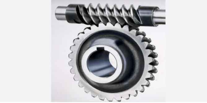
Worm gear mechanisms are indispensable in actuators and motion control systems due to their inherent self-locking capability, which prevents reverse power transmission from the load to the motor. However, in vibrational environments—common in aerospace, automotive, and industrial machinery—this self-locking property can degrade, leading to catastrophic failures. During a random vibration test of a prototype actuator, we observed unintended valve opening despite the motor being de-energized. This anomaly traced back to the worm gear’s inability to maintain self-locking under dynamic loads. Our study aimed to diagnose the root causes, redesign critical components, and validate solutions through simulations and physical testing.
Worm Gear Self-Locking Fundamentals
The self-locking behavior of a worm gear pair hinges on the relationship between the lead angle (γγ) of the worm and the effective friction angle (ββ) of the mating surfaces. The condition for self-locking is derived from the equilibrium of forces on the worm thread:γ≤βγ≤β
Here, γ=arctan(Z1q)γ=arctan(qZ1), where Z1Z1 is the number of worm threads and qq is the diametral quotient. The friction angle β=arctan(f)β=arctan(f), with ff being the coefficient of friction.
Key Factors Affecting Friction Coefficient (ff)
- Material Pairing: Table 1 summarizes friction coefficients for common worm gear material combinations.
- Relative Sliding Velocity (VsVs): As VsVs increases, ff decreases (Table 2).
- Static vs. Dynamic Friction: Static friction (fsfs) is higher than dynamic friction (fdfd) (Table 3).
Table 1: Friction Coefficients for Worm Gear Material Pairs
| Worm Material | Wheel Material | ff Range |
|---|---|---|
| Steel | Steel | 0.10–0.15 |
| Steel | Bronze | 0.10–0.18 |
| Steel | Brass | 0.03–0.15 |
Table 2: Friction Coefficient vs. Sliding Velocity
| VsVs (m/s) | 0.01 | 0.1 | 1.0 | 5.0 | 10.0 |
|---|---|---|---|---|---|
| ff | 0.11 | 0.08 | 0.045 | 0.022 | 0.016 |
Table 3: Static vs. Dynamic Friction Coefficients
| Material Pair | fsfs | fdfd |
|---|---|---|
| Steel-Steel | 0.242 | 0.088 |
| Steel-Bronze | 0.330 | 0.180 |
Failure Mechanism Under Vibration
In static conditions, self-locking is assured if γ≤βγ≤β. However, vibrational loads introduce two destabilizing factors:
- Reduced Effective Friction: Oscillatory motion transitions static friction to dynamic friction, lowering ββ.
- Rotational Torque from Imbalance: Motor rotor and worm shaft imbalances generate parasitic torque (TrotTrot), overcoming the friction torque (TfricTfric):
Trot>Tfric=μ⋅N⋅rTrot>Tfric=μ⋅N⋅r
where μμ is the friction coefficient, NN is the normal force, and rr is the pitch radius.
Quantifying Rotational Torque
For our actuator, vibrational testing revealed . This exceeded the available TfricTfric due to diminished ff under sliding conditions.
Magnetic Stabilization: A Novel Solution
To counteract TrotTrot, we designed a non-contact magnetic stabilization mechanism. The system employs radially magnetized permanent magnets arranged circumferentially on the worm shaft, generating a counter-torque (TmagTmag) opposing unwanted rotation.
Design Parameters
- Magnet Configuration: Six NdFeB magnets (Br=1.18 TBr=1.18T) embedded in a stainless-steel hub.
- Torque Calculation: For a magnet at angle θθ, the torque is:
Tmag=n⋅B⋅A⋅l⋅sin(θ)Tmag=n⋅B⋅A⋅l⋅sin(θ)
where nn = number of magnets, BB = magnetic flux density, AA = pole area, and ll = effective lever arm.
Table 4: Simulated Magnetic Torque at Key Angles
| θθ (°) | 0 | 15 | 30 | 45 | 60 |
|---|---|---|---|---|---|
| TmagTmag (mN·m) | 0 | 0.52 | 4.54 | 2.31 | 0 |
The peak at θ=30∘θ=30∘, sufficient to offset TrotTrot.
Simulation and Validation
Finite Element Analysis (FEA)
Using ANSYS Maxwell, we modeled magnetic flux distribution and torque profiles (Figure 1). Key observations:
- Axial magnetic force per magnet: Faxial≈0.12 NFaxial≈0.12N.
- Total counter-torque at 30∘30∘: .
Power Consumption Analysis
The additional current (IaddIadd) due to TmagTmag was calculated as:Iadd=TmagkT=4.5451×3 A≈0.26 AIadd=kTTmag=514.54×3A≈0.26A
where . This fell within the motor’s 5 A tolerance.
Experimental Verification
Post-modification vibration tests (4 hours, Y-axis random vibration) confirmed:
- No unintended valve opening occurred.
- Current draw increased by 0.22 A0.22A, aligning with simulations.
Table 5: Performance Comparison
| Parameter | Pre-Improvement | Post-Improvement |
|---|---|---|
| Self-Locking Stability | Failed at 4h | Stable at 4h |
| Current Draw (A) | 3.00 | 3.22 |
Key Innovations and Applications
- Magnetic Stabilization: A compact, non-contact solution to enhance worm gear啮合 stability.
- Universal Applicability: Suitable for high-precision actuators in aerospace and robotics.
- Minimal Power Impact: <10% increase in current consumption.
Conclusion
This study demonstrates that magnetic stabilization effectively mitigates self-locking failure in worm gear systems under vibrational loads. By integrating permanent magnets into the worm shaft, we achieved a counter-torque of , surpassing the disruptive rotational torque. The solution’s simplicity, reliability, and low power penalty make it viable for diverse worm gear applications. Future work will explore adaptive magnetic arrays and temperature-resistant materials for extreme environments.