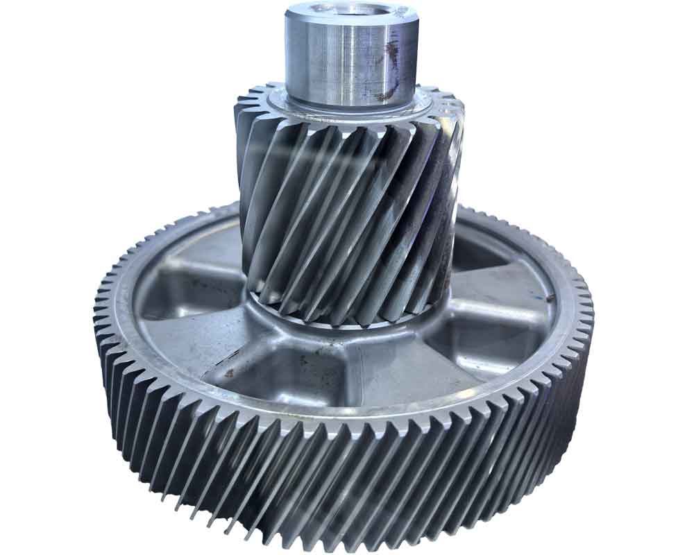
Equal-height spiral bevel gears demonstrate superior performance characteristics including high transmission efficiency, strong load-bearing capacity, smooth operation, and minimal noise generation. These advantages make them indispensable in automotive, aerospace, and aviation applications. Traditional manufacturing of these gears requires extensive trial cutting, which consumes significant time and resources. Our research establishes a comprehensive methodology for simulating and optimizing the gear cutting process using finite element analysis, significantly reducing experimental iterations while enhancing production efficiency.
1. Cutting Trajectory Formulation
The manufacturing process employs the face hobbing method, where the cutter head rotates on its axis while simultaneously revolving around the cradle axis to generate extended epicycloidal tooth profiles. The mathematical foundation for this process is defined by the following coordinate systems and equations:

The machine coordinate system originates at point O (machine center), with the ij-plane perpendicular to the cradle axis. Key parameters include:
- Radial distance S between O and cutter head center OC
- Angular orientation q between OOC and machine plane
- Cutter radius rC and tool-tip radius r0
The tool-tip radius varies for inside and outside blades:
$$r_0 = r_C \pm 0.5W_G$$
where positive denotes inside blades and negative denotes outside blades. Position vector for tool-tip M0:
$$\mathbf{r_{M_0}} = [S\cos q + r_0 \sin(q – \theta)]\mathbf{i} + [S\sin q + r_0 \cos(q – \theta)]\mathbf{j}$$
Unit normal vector n and tangential vector t along the cutting edge:
$$\mathbf{n} = \cos\phi\sin(q – \theta)\mathbf{i} + \cos\phi\cos(q – \theta)\mathbf{j} – \sin\phi\mathbf{k}$$
$$\mathbf{t} = \sin\phi\sin(q – \theta)\mathbf{i} + \sin\phi\cos(q – \theta)\mathbf{j} – \cos\phi\mathbf{k}$$
Cutting surface equation for arbitrary point M relative to M0:
$$\mathbf{r_M} = \mathbf{r_{M_0}} – s\mathbf{t}$$
where s represents distance along the cutting edge.
2. Finite Element Simulation of Gear Cutting
We implemented a multi-parameter simulation approach using AdvantEdge FEM software to analyze cutting mechanics under diverse conditions. The workflow encompasses:
2.1 Geometric Modeling
Simplified 3D models were developed in UG NX and imported into AdvantEdge:
- Workpiece: AISI-4120 alloy steel (20CrMnMo equivalent, 248 BHN hardness)
- Tool: Carbide-General carbide inserts with variable rake face angles
- Mesh Parameters: Tool min size 0.2mm, Workpiece min size 0.1mm
2.2 Trajectory Approximation
Actual epicycloidal motion was approximated using linear feed due to software constraints:
Actual Toolpath:
$$x = 88\cos\alpha + 138.68\cos(50.85^\circ – 0.35\alpha)$$
$$y = 88\sin\alpha + 138.68\sin(50.85^\circ – 0.35\alpha)$$
Simulated Toolpath:
$$x = 88\cos\alpha + \frac{105.48\alpha}{\pi} + 86.31$$
$$y = 88\sin\alpha + \frac{109.692\alpha}{\pi} + 106.43$$
2.3 Simulation Parameters
| Parameter | Baseline Value | Variation Range |
|---|---|---|
| Cutting Speed (v) | 180 m/min | 150-210 m/min |
| Feed Rate (f) | 0.01 mm/tooth | 0.01-0.02 mm/tooth |
| Rake Face Angle (φ) | 12° | 8.5°-15.5° |
| Cutting Rotation | 50° | Constant |
2.4 Gear Cutting Simulation Results
Simulations revealed significant correlations between gear cutting parameters and mechanical/thermal outcomes:
Cutting Force Dynamics:
| Parameter Change | Y-Direction Force (Fy) | Temperature (Tmax) |
|---|---|---|
| v ↑ 150→210 m/min | 12.5% ↓ | 22.8% ↑ |
| f ↑ 0.01→0.02 mm/t | 18.3% ↑ | 5.7% ↑ |
| φ ↑ 8.5°→15.5° | 8.4% ↓ | Min at 12° |
Mathematical relationships derived from simulation data:
$$F_y(v) = 1850 – 4.2v + 0.011v^2\ \text{(R²=0.96)}$$
$$T_{\max}(v) = 320 + 1.8v – 0.004v^2\ \text{(R²=0.93)}$$
$$F_y(f) = 1120 + 31500f\ \text{(R²=0.98)}$$
Optimal rake face angle minimizes thermal load:
$$T_{\min}(\phi) = 482 + 18.5(\phi – 12)^2\ \text{at}\ \phi=12^\circ$$
3. Experimental Validation
Cutting trials were performed on a Gleason Phoenix 175HC CNC using the simulation-optimized parameters:
3.1 Gear Cutting Setup
- Workpiece: 10-tooth spiral bevel gear (mn=5.6mm, β=50°)
- Tooling: Tri-ac 88mm left-hand cutter with 17 blade groups
- Parameters: v=180 m/min, f=0.01 mm/tooth, φ=12°
- Runout Control: < 2μm total indicator reading
3.2 Quality Verification
Post-cutting evaluation confirmed manufacturing excellence:
| Inspection Method | Metric | Result | DIN 3965 |
|---|---|---|---|
| Visual Inspection | Surface Roughness | Ra ≤ 1.6μm | Grade 7 |
| Roll Test | Contact Pattern | Central Position | Optimal |
| Klingelnberg P40 | Single Pitch Error (fp) | 12μm | Grade 7 |
| Adjacent Pitch Error (fu) | 9μm | Grade 6 | |
| Pitch Variation (Rp) | 15μm | Grade 7 | |
| Cumulative Pitch Error (Fp) | 28μm | Grade 7 | |
| Runout Error (Fr) | 20μm | Grade 6 |
4. Conclusion
This research establishes a comprehensive methodology for optimizing equal-height spiral bevel gear cutting processes through advanced simulation techniques. The validated findings demonstrate:
- The derived cutting trajectory equations accurately model the complex kinematics of spiral bevel gear cutting
- Finite element simulation effectively predicts cutting forces and thermal behavior during gear cutting operations
- Cutting speed increase from 150 to 210 m/min reduces cutting forces by 12.5% but increases temperature by 22.8%
- 12° rake face angle minimizes thermal loading while maintaining favorable chip formation
- Experimental verification confirms that simulation-optimized parameters produce DIN 3965 Grade 7 gears
The developed methodology significantly reduces trial cutting requirements in gear cutting operations while enhancing manufacturing precision. Future work will extend this approach to hard machining applications and develop real-time adaptive control systems based on the established models.
