
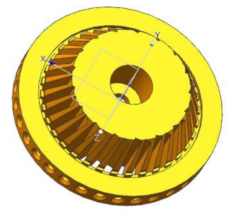
As shown in Figure 1, it is the three-dimensional model of the cutter head established on UG. The contour spiral bevel gear milling cutter head is welded from the outer ring of the milling cutter head of the main body of the milling cutter head. The contour spiral bevel gear milling cutter head is equipped with an inner cutter bar and an outer cutter bar. The inner cutter bar on the left side of the cutter head and the outer cutter bar on the right side form a pair of cutting cutter bars. The inner cutter bar cuts the convex surface of the bevel gear and the outer cutter bar cuts the concave surface of the bevel gear. According to the rotation direction, the contour spiral bevel gear milling cutter head is divided into left rotation milling cutter head and right rotation milling cutter head. From the cutter tip of the cutter bar installed on the contour spiral bevel gear milling cutter head, if the rotation direction of the contour spiral bevel gear milling cutter head is clockwise, it is called left rotation cutter head; If the rotation direction of the spiral bevel gear milling cutter head with equal height teeth is counterclockwise, it is called the right rotation cutter head. The cutting direction of equal height gear and the rotation direction of equal height spiral bevel gear milling cutter head complement each other. The outer side of the main body of the contour spiral bevel gear milling cutter head is provided with a large number of cutter slots for installing the milling cutter strips, and the corresponding cutter slots are provided with threaded holes for assembling screws, which can ensure the fixed position of the milling cutter strips.
This kind of milling cutter disc for machining equal height spiral bevel gear is used to install milling cutter strips with equal distance, that is, the reference point of the inner and outer cutter strips is on the same circle, and the milling cutter strips for cutting the convex and concave surfaces of the gear are on an imaginary involute.
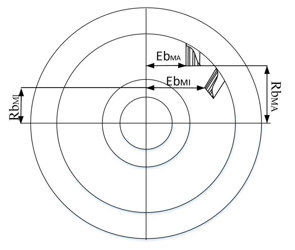
The axial distance ebmi and EBMA from the cutter groove positioning line to the center of the equal height spiral bevel gear milling cutter head, and the radial distance corresponding to other directions in the center of the equal height spiral bevel gear milling cutter head, and the radial distance between the inner cutter groove and the outer cutter groove in the center of the cutter head are rbmi and RbmA, which are important design parameters of the equal height spiral bevel gear milling cutter head. As shown in Figure 2, they are the specific position in the milling cutter head when a group of milling inserts are inserted into the cutter head.