Face milling (FM) and face hobbing (FH) are widely used in machining bevel gears, hypoid gears and other complex curved surface gears. These two methods use the cutter head to cut the gear from the top to the root of the tooth. The cutting edge is divided into inner cutter and outer cutter on each concentric circle, but their cutter heads and blades are different in arrangement. FM adopts single division processing, which has low processing efficiency, more equipment and high production cost; FH adopts continuous indexing method, which can significantly shorten the production cycle and reduce the production cost. In this paper, FH hypoid gear is taken as the research object. Firstly, all kinds of transformation matrix involved in the machining process of FH hypoid gear are deduced, and the matching gear model is obtained. Accurate tooth surface model will help to improve the accuracy of tooth surface contact analysis.

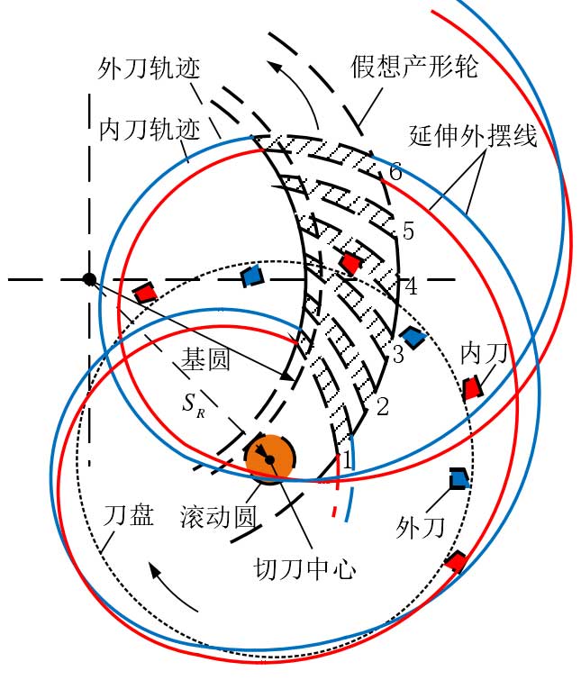
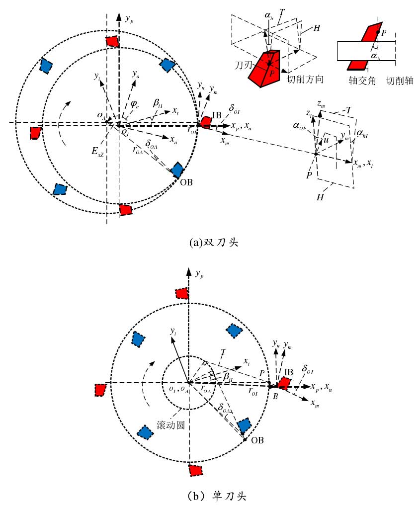
FH machining method is a two-sided processing technology which can simultaneously cut both sides of the tooth surface on the same machine tool. Roughing and finishing can be done at one time. As shown in Fig. 1, the inner and outer cutter groups on the cutter head respectively process the concave convex surface of the gear. In the continuous indexing process, a cutter group moves in a slot, and the workpiece rotates in the opposite direction, so that the next cutter group can enter the next slot. Fig. 2 shows the FH cutter head coordinate system. There are Z0 groups of cutter groups in the face rolling cutter head. Each group of cutter groups is composed of at least one inner cutter and an outer cutter. The cutter groups are arranged in strictly specified relative positions to realize continuous transposition.

In order to simulate the motion process of the double cutter heads, the inner and outer tool heads rotate around two parallel axes at the same speed. The origin OI and OA are the rotation centers of the inner and outer cutter heads respectively, and the eccentricity of the double cutters
Exz and direction angle φ e describe the position relationship of the two origin points. The inner tool radius ROI is generally equal to the nominal tool radius r0, and the outer tool radius is roa. The other parameters of the double cutter head include initial installation angle β I, offset angle δ 0, rake angle α h, tooth profile angle α 0 and cutter number Z0. Rake angle α h is usually used to accurately reflect the offset of tooth contact.
